42 bluac5 s/q hardware manual – Applied Motion BLuAC5-Q User Manual
Page 42
42
BLuAC5 S/Q Hardware manual
920-0049 Rev. C
12/8/2014
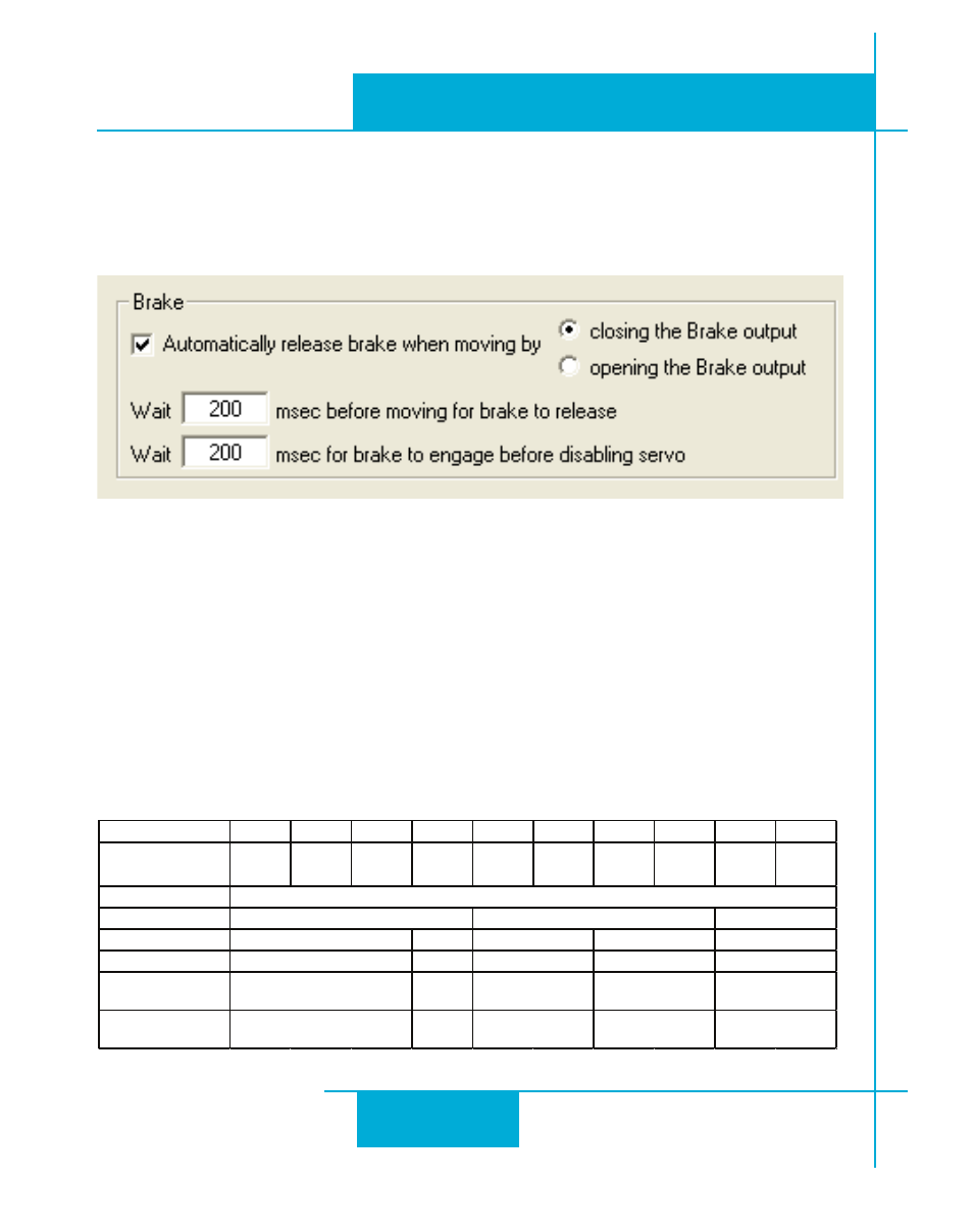
The holding brakes of M Series servo motors are fail-safe brakes, which means they are en-
gaged when no power is applied to the brake. When setting up a servo drive in Quick Tuner,
be sure to set the Brake output options in the “Inputs-Outputs” tab as shown in the diagram
below. Make sure to select the check box for “Automatically release brake when moving by”
and selecting the radio button “closing the Brake output”.
The engaging and disengaging of the brake is done automatically by the servo drive. When
the drive is enabled and not faulted the brake will be disengaged. When the drive is disabled
and/or faulted the brake will be engaged.
There are two time delays associated with the Brake output function which are also set in
Quick Tuner (see diagram above). The first time delay controls how long the drive will delay
a move command if the move command immediately follows the disengagement of the brake.
The second time delay controls how long the drive will delay disabling the motor after engag-
ing the brake when a motor disable command is issued.
Reference Information
Below is a summary of specifications for the integral holding brakes available with M Series
servo motors.
Motor Power (W)
30
50
100
100
200
400
200
400
600
750
Motor Frame Size
NEMA 17
40 mm
NEMA 17
40 mm
NEMA 17
40 mm
NEMA 23
60 mm
NEMA 23
60mm
NEMA 23
60 mm
NEMA 34
80 mm
NEMA 34
80 mm
NEMA 34
80 mm
NEMA 34
80 mm
Rated Voltage
Static Friction (in-lb)
Input Power (W)
9
Input Current (A)
0.375
Armature Release
Time (msec Max)
20
Armature Pull-In
Time (msec Max)
40
9.5
0.39
50
80
20
50
9.5
0.39
50
80
20
40
24 VDC
2.83
11.24
22.5
5
0.2
9
0.375