Status & error display leds, Serial comm tx & rx led, Bus voltage indication led – Applied Motion BLuAC5-Q User Manual
Page 7: Serial comm tx & rx led bus voltage indication led, 7bluac5 s/q hardware manual, Standard on bluac5-si option on -s, -q, In/out 1 connector (db25f), Digital inputs, Digital outputs, Analog inputs
7
BLuAC5 S/Q Hardware manual
920-0049 Rev. C
12/8/2014
DC Bus
Motor
Encoder
IN / OUT 1
IN / OUT 2
PC/MMI
RS-485/422
C B A
GND
TX-
TX+
RX-
RX+
COMM
Status
Regen
GND
+24VDC
Input
320V pk
User Out
+24VDC
GND
CLAMP RES
EXT
BUS
BRAKING L1
L2/N
L3
AC PO
WER
G
Error Codes
Position Limit
CCW Limit
CW Limit
Ov
er Temp
Ov
er Voltage
Under
Voltage
Ov
er Current
Current Limit
Hall Bad
Encoder Bad
Memor
y F
ailed
Regen F
ailed
Comm Error
Position Mode
Velocity Mode
Torque Mode
Step Mode
Oper
ating Modes
Fron
t Vie
w
X CO
MM
ON
X7 / C
W Lim
it
X3 / S
ervo
Ena
ble
X5
X4 / A
larm
Res
et
Analo
g IN
-
Analo
g IN
+
X2 / D
IR-
X2 / D
IR+
X1 / S
TEP
/ PW
M+
X1 / S
TEP
/ PW
M-
GND
GND
A+
A-
B+
B-
Z+
Z-
+5V
OU
T
Y CO
MM
ON
Y3 / A
LAR
M
Y2 / I
NPO
SN
Y1 / B
RAK
E
18 17
16 15
14
13 12
11 10
9 8
7 6
5 4
2
3
1
19
20
21
22
23
24
25
Encoder
Outputs
X6 / C
CW
Lim
it
18
17
16
15
14
13
12
11
10
9
8
7
6
5
4
2 3
1
19 20
21 22
23 24
25
+5V
Out 1
-
Out 2
+
Out 1
+
Ain C
om
N/C
Ain 1
IN 8-
COM
IN 5
IN 6
IN 7+
IN 8+
IN 7-
IN 4
IN 1
COM
IN 2
COM
IN 3
Out 2
-
Out 3
+
Out 3
-
Out 4
+
Out 4
-
ena
bled when
flashing
Driv
e Disab
led
Si Mode
INT
rotating segment indicates Q
prog
ram r
unning.
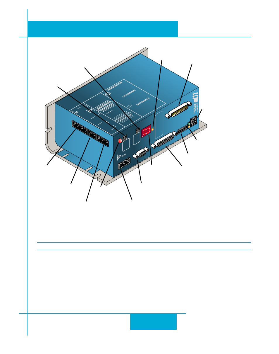
IN/OUT 2
IN/OUT 1
IN/OUT 1 Connector (DB25F)
•
digital inputs
•
digital outputs
•
analog inputs
•
encoder output
HD-15 connector
•
motor feedback
screw terminal
plugable connector
•
motor
plugable screw
terminal connector
•
RS-485 port
comm status LEDs
•
Rx (Green)
•
Tx (Amber)
RJ11 connector
•
RS-232 port
Always use the blue & white Applied Motion
screwdriver to tighten the screw terminal connectors.
Larger screwdrivers may remove the plastic dimples
that prevent the screws from falling out.
plugable screw
terminal connector
•
AC input 100-260VAC
plugable screw
terminal connector
•
Dynamic Braking Resistor
plugable screw
terminal connector
•
External Regen Resistor
IN/OUT 2 Connector (DB-25M)
-SE and -QE only
•
digital inputs
•
digital outputs
•
analog input
Status LED
•
Regen
Seven Segment
LED
•
status codes
•
error Codes
Status LED
•
DC Bus Voltage
present
plugable screw
terminal connector
•
User 24 volt output
plugable screw
terminal connector
•
24 volt (Keep Alive)
input
Standard on BLuAC5-Si
Option on -S, -Q
Status & Error Display LEDs
Serial Comm Tx & Rx LED
Indicates that data is being recieved or transmitted through the RS-232 or RS-485 serial
ports. Green indicates “Receiving”. Red indicates “Transmitting”
Bus voltage indication LED
Indicates when there is DC Bus voltage present on the drive. Servo drive cover should not be
removed when this LED is illuminated.