Rj45 connector setups – Doremi AccessLink User Manual
Page 31
FAL.OM.002372.DRM
Page 31 of 62
Version 1.6
Doremi Labs
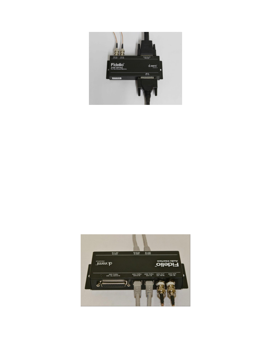
Figure 32: Audio Interface for DB25 Setups
3.3.1.2 RJ45 Connector Setups
If your setup consists of using RJ45 connectors, you will need to disconnect the RJ45
cables from your server or IMB.
Then connect these cables to the connectors on the Fidelio Audio Interface Box labeled,
“AES THRU CH 1-6,” and the other cable to the connector that reads, “AES THRU CH
9-
14” (Figure 33).
The other ends on these cables are to remain connected to your audio processor,
respectively.
Using the short RJ45 cable provided, connect one cable into the CH 1-8 AES OUT on
the server or IMB and the other end into the AES IN CH 1-8 connector on the Fidelio
Audio Interface box.
Using the other short RJ45 cable provided, connect one cable into the CH 9-16 AES
OUT on the server or IMB and the other end into the AES IN CH 9-16 connector on the
Fidelio Audio Interface box.
Figure 33: Audio Interface for RJ45 Setups