5 installing cables and power, System cable diagram, Figure 2-7. system cable diagram – Adept AnyFeeder User Manual
Page 25
Installing Cables and Power
Adept AnyFeeder User’s Guide, Rev. B
25
2.5
Installing Cables and Power
This section describes the electrical installation procedure for the Adept AnyFeeder. The
Adept AnyFeeder requires the following cable connections:
• the 24 VDC power cable (supplied)
• the RS232 serial communications cable (supplied)
• the DIO (Digital I/O) cable (supplied)
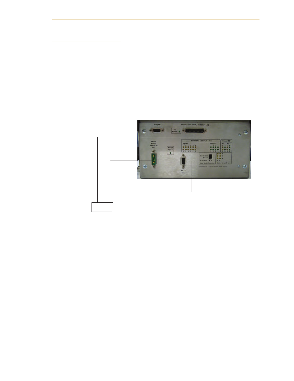
System Cable Diagram
Figure 2-7. System Cable Diagram
NOTE: Refer to your robot user’s guide for additional system cable
information.
NOTE: The Adept AnyFeeder is equipped with fuses to protect the
internal components. The motor power 24 VDC input is protected with a
10 Amp fuse, and the parallel I/O 24 VDC lines are protected with a 3
Amp fuse. These fuses can be replaced in the field. If you suspect a
problem with one or both of these fuses, contact Adept Customer Service
(see
) for part information and instructions.
AnyFeeder Interface Panel
DIO Cable
Pins 13, 25: +24 VDC
Pins 12, 24: Ground
Red: +24 VDC
Blue: Ground
Black: Shield
Note: To serial port on Adept
SmartController (for V+/AIM
applications) or to user-supplied
PC (for ACE/iSight applications)
User-supplied
24 VDC
power supply
Black: Shield
Ground to
Power Supply
Case