4 waveform management [3pi controller only – AMETEK MX Series Rev: AY User Manual
Page 127
User Manual – Rev AY
AMETEK Programmable Power
MX Series
127
required operating mode so the unit powers up in the correct voltage mode
1
. If not, the mode
must be selected before applying output power to prevent applying to wrong type of voltage.
4.4 Waveform Management
[3Pi Controller only]
The MX Series with 3Pi controller employs independent arbitrary waveform generators for each
phase. This allows the user to create custom waveforms. In addition, three standard waveforms
are always available. This chapter covers issues that relate to defining, downloading and
managing custom waveforms.
4.4.1 Standard Waveforms
For most AC applications, a sine wave shape is used. The sine wave is one of the standard
waveforms provided on all MX Series models. This standard sine wave is always available and is
the default waveform at power-on. On MX models with the 3Pi controller, two more standard
waveforms are available, square and clipped.
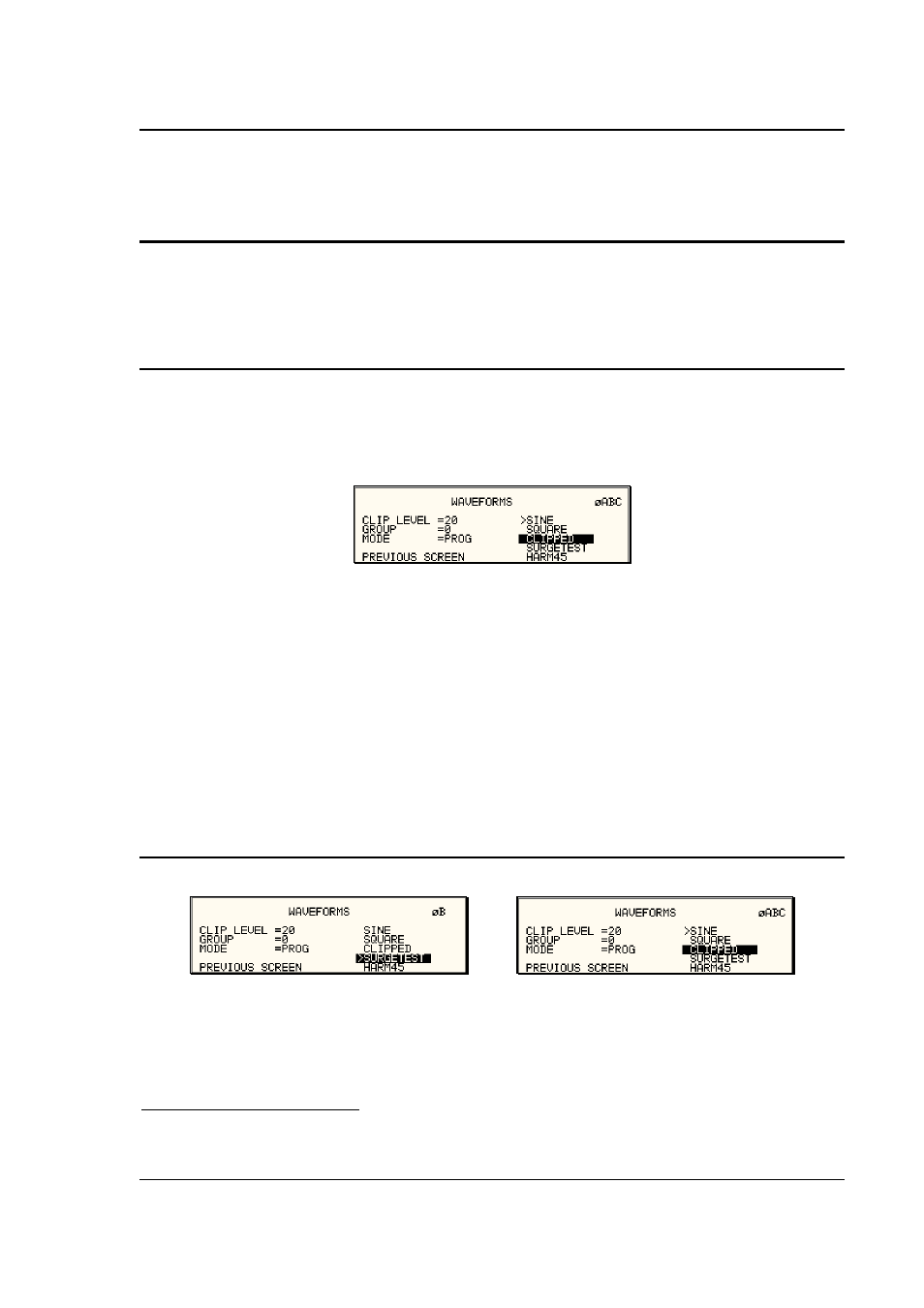
Figure 4-31: Selecting a Waveform
The square wave provides a high frequency content waveform with relative fast rise and fall
times. Due to AC amplifier bandwidth limitations, the frequency content of the standard square
wave has been kept within the amplifier’s capabilities. As the fundamental frequency is
increased, the relative contribution of higher harmonics is reduced.
The clipped sine wave may be used to simulate voltage distortion levels to the unit under test.
The total harmonic distortion level may be programmed in percent using the CLIP LEVEL field of
the WAVEFORMS menu. Changing the distortion level of the CLIP waveform forces the AC
source to regenerate the CLIPPED sine wave’s data points and reload the waveform register with
the newly requested data. This process requires the output to be dropped briefly. To avoid
interrupting the voltage output to the unit under test, select a different waveform such as the
standard sine wave first, change the clip level and change the waveform back to the CLIPPED
sine wave. This will avoid any output interruption.
4.4.2 Phase Selection
Figure 4-32: Selecting Waveforms for Single Phase or All Phases
Different waveforms may be selected for each phase. The number of custom waveforms from
which to select remains 50 but each phase can be assigned a different custom or standard
waveform. The specific output phase for which the wave shape is programmed is selected with
1
If the mode is changed after power up and after the output relay is closed for the first time after power up, the measurement
offset calibration may not be correct. A phase mode change (-3Pi only) may be used to recalibrate the measurement offset.