3 input selection, 1 input switch, 2 microphone input – API Audio The Channel Strip User Manual
Page 10: 3 instrument input
3.3 Input Selection
The 512C Preamp can receive three (3) input sources:
•
MIC (Microphone): Rear panel female XLR microphone input with switchable 48V phantom power
•
INST (Instrument): Front panel ¼” unbalanced -10dBu instrument level input
•
LINE: Rear panel ¼” TRS balanced +4dBu line level input
3.3.1 Input
Switch
The INPUT switch also serves as a peak indicator when the output of the preamp exceeds +27dBu.
The INPUT switch will change color as follows to indicate peak levels:
The INPUT switch is used to select the input source. It is a momentary selector which
cycles through the three input sources, Mic-Instrument-Line. It changes color to
indicate which source is currently selected.
•
MIC (Microphone): Illuminated in blue
•
INST (Instrument): Illuminated (yellow)
•
Line: Not illuminated (white)
•
MIC (Microphone): Changes from blue to violet
•
INST (Instrument): Changes from yellow to orange
•
Line: Changes from white to red
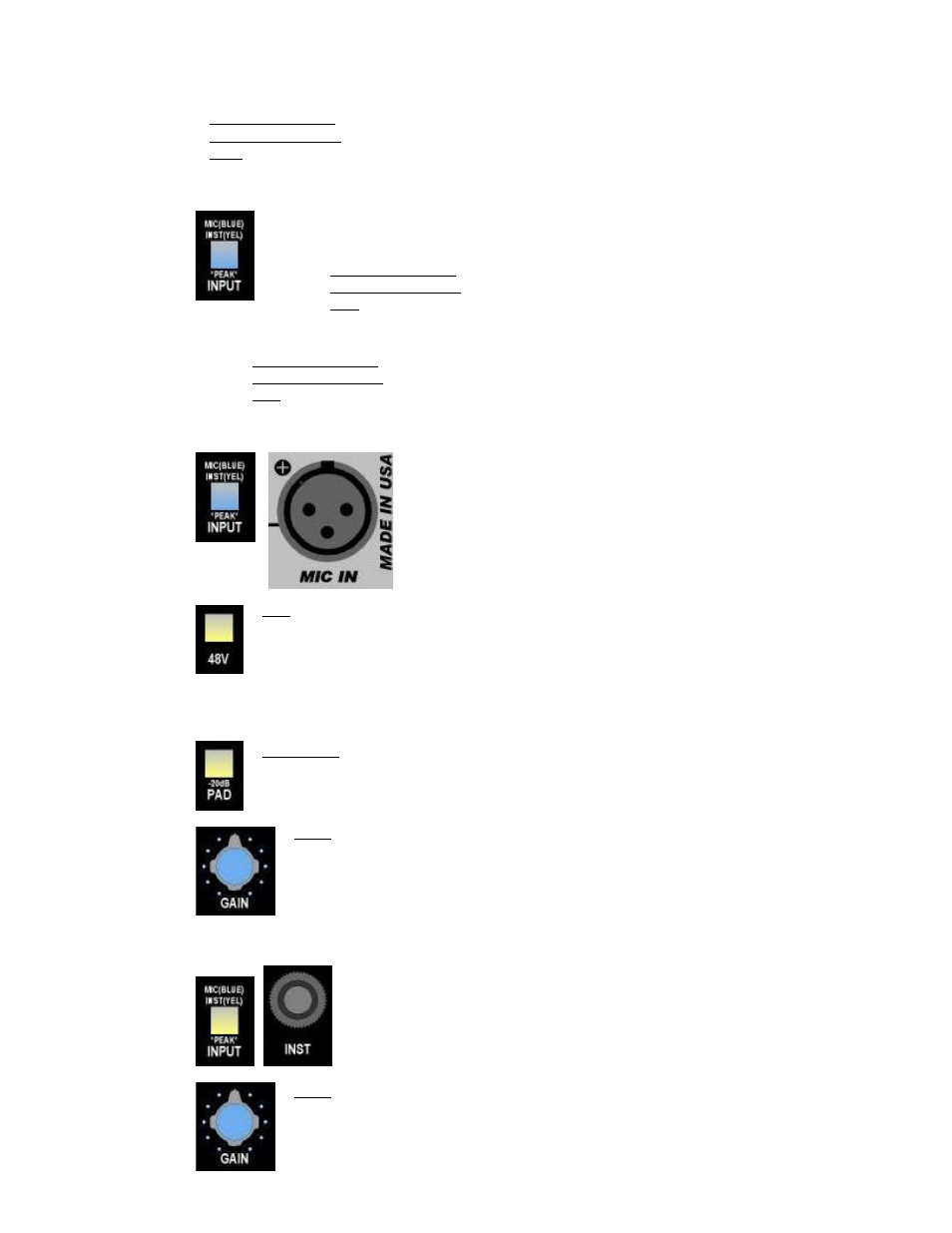
3.3.2 Microphone
Input
48V: Provides 48 volt phantom power to the MIC IN female XLR connector
•
Illuminates when engaged
IMPORTANT:
Caution should be exercised when engaging phantom power!
Damage can occur if phantom power is applied to some audio
devices, including most ribbon microphones. The Channel Strip
output should also be muted (CUT) when engaging the 48V switch.
Select the microphone input (MIC) by pressing the INPUT switch
until it illuminates in blue. The MIC IN connection on the rear
panel will be the active input.
•
Female XLR microphone input
•
48v phantom power
•
-20dB pad
•
INPUT switch illuminates in blue when engaged
•
Violet peak indication when output exceeds +27dBu
-20dB PAD: Inserts a -20dB attenuator after the microphone input
•
Illuminates when engaged
GAIN: Microphone preamp level control
•
34dB nominal gain
•
68dB maximum gain
•
14dB minimum gain with -20dB pad engaged
3.3.3 Instrument
Input
Select the instrument input (INST) by pressing the INPUT switch until it
illuminates. The ¼” INST jack on the front panel will be the active input.
•
-10dBu instrument level input
•
Unbalanced, high-impedance input (¼” tip-sleeve)
•
INPUT switch illuminates (yellow) when engaged
•
Orange peak indication when output exceeds +27dBu
GAIN: Instrument preamp level control
•
14dB minimum
•
50dB maximum gain
•
No pad
9