3 high frequency band, 4 band-pass filter, 3 equalizer routing – API Audio The Channel Strip User Manual
Page 23: 1 equalizer post compressor (default signal flow), 2 equalizer pre compressor
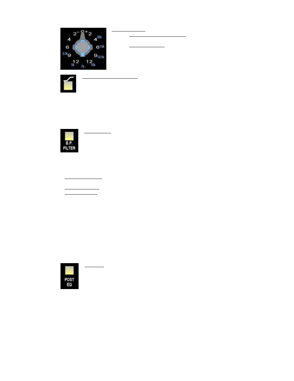
5.2.3 High Frequency Band
High Frequency:
•
Center Frequency (knob): 2.5kHz, 5kHz, 7kHz, 10kHz, 12.5kHz,
15kHz, 20kHz
•
Boost/Cut (ring): +/- 12dB
•
Switchable shelving
High Frequency Shelving: Changes the high frequency band from a peaking EQ to a
shelving EQ
•
All frequencies above the selected center frequency will be boost or cut
•
Illuminates when engaged
5.2.4 Band-Pass Filter
A -3dB @ 50Hz to 15kHz band-pass filter can be inserted in the 550A Equalizer circuit by engaging
the B.P. FILTER switch.
5.3 Equalizer Routing
B. P. FILTER: Activates the band-pass filter
•
Illuminates when engaged
There are three (3) routing options for 550A Equalizer:
•
Post Compressor: The 550A Equalizer is located after the compressor and before the output
section (default signal flow)
•
Pre Compressor: The 550A Equalizer is located after the preamp and before the compressor
•
Hard Bypassed: The 550A Equalizer is removed completely from the audio path
5.3.1 Equalizer Post Compressor (Default Signal Flow)
In the default signal flow (no routing switches engaged), the 550A Equalizer receives the output of
the 527 Compressor.
•
550A Equalizer will interface via the SECOND EFFECT jacks on the rear panel
•
527 Compressor will interface via the FIRST EFFECT jacks on the rear panel
5.3.2 Equalizer Pre Compressor
When the POST EQ switch is engaged, the 550A Equalizer receives the output of the 527
Compressor and is interfaced via the FIRST EFFECT jacks on the rear panel.
POST EQ: Moves the 527 Compressor to post the 550A Equalizer in the audio path
•
550A Equalizer will interface via the FIRST EFFECT jacks on the rear panel
•
527 Compressor will interface via the SECOND EFFECT jacks on the rear panel
•
Illuminates when engaged
22