1 side chain input, 2 dc link, 5 remote mute control – API Audio The Channel Strip User Manual
Page 30
7.4 527 Compressor Side Chain and DC Link Connections
The 527 Compressor provides two methods of external control:
•
Side Chain Input
•
DC Link
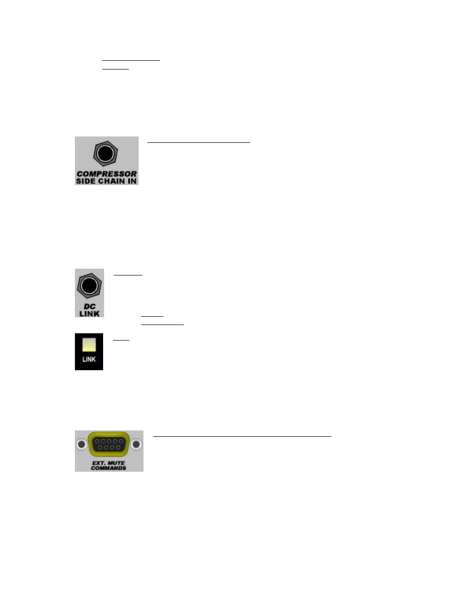
7.4.1 Side Chain Input
The compressor Side Chain is the detector path that contains the THRUST® filter and RMS detector.
When the compressor type is set to NEW, the Side Chain is fed from a split of the 527 Compressor input
signal. When the NEW type is selected, the Side Chain signal can alternately be fed from an external
signal via the COMPRESSOR SIDE CHAIN IN jack on the rear panel.
7.4.2 DC Link
The 527 Compressor in The Channel Strip can be linked with 527 Compressors in other units for stereo
and multichannel applications. When connected together and the LINK switches are engaged, the DC
control voltages from all units are summed together. This results in the same control changes being
applied to all compressors. While this is not a “Master/Slave” configuration, the Threshold,
Attack/Release Times, and Ratio of all units should be set to the same value to prevent one channel
from generating a disproportionate contribution to the summed control voltage.
COMPRESSOR SIDE CHAIN IN: Input to the 527 Compressor detector path
•
Inserting a plug will replace the Side Chain signal
•
Only available when the NEW compressor type is selected
•
Switching ¼” tip-ring-sleeve jack
•
+4 dBu line level input
•
Balanced, low-impedance
DC LINK: Control voltage input/output jack for the 527 Compressor
•
Active only when LINK switch is engaged
All DC LINK cables are ¼” TRS phone plugs wired tip-to-tip, ring-to-ring, and sleeve-
to-sleeve
•
Stereo: Cable with a ¼” TRS on each end
•
Multichannel: Cable with multiple ¼” TRS plugs
LINK: Activates the DC control voltage summing with other units
•
Illuminates when engaged
7.5 Remote Mute Control
The soft mute (CUT) can be remotely controlled via the EXT. MUTE COMMANDS connector on the rear
panel. The remote circuit operates in parallel with the on-board CUT switch, but overrides the on-board
CUT switch when activated.
9-pin D-sub pin-out for remote mute control:
EXT. MUTE COMMANDS (External Mute Commands): Control port for the soft
mute (CUT) switch
•
Overrides on-board CUT switch when activated
•
9-pin D-sub connector
•
Pin 1 – 5V gnd
•
Pin 6 – +5V
•
Pin 9 – Cut switch output active low
•
Pin 5 – External mute command input active +5V high
29