6 rear panel signal flow – API Audio The Channel Strip User Manual
Page 31
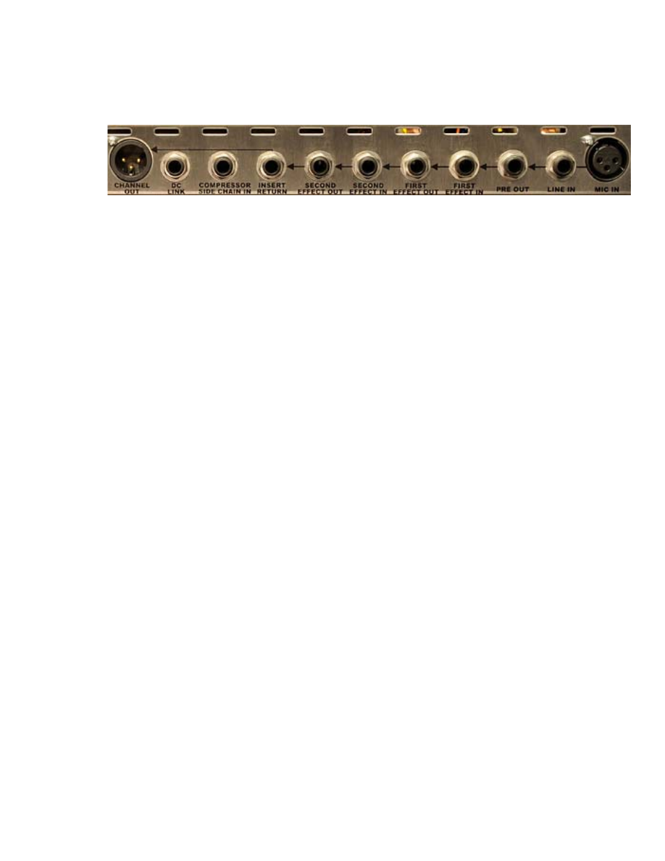
7.6 Rear Panel Signal Flow
The Channel Strip signal flow is illustrated by the right-to-left order of the unit’s rear panel. The order of
these interfaces remains constant regardless of the order of the 527 Compressor and 550A Equalizer in
the signal path.
Second First
Output <--------------------- Insert <----- Effect <------------ Effect <------------ 512C Preamp
•
The PRE OUT is “half-normalled” to feed the FIRST EFFECT IN
•
The FIRST EFFECT IN feeds the first processor in the audio path (normally the 527
Compressor*)
•
The FIRST EFFECT OUT is “half-normalled” to feed the SECOND EFFECT IN
•
The SECOND EFFECT IN feeds the second processor in the audio path (normally the 550A
Equalizer*)
•
The SECOND EFFECT OUT is “half-normalled” to feed the 325 Line-Driver input
* Engaging the POST EQ switch will move the 527 Compressor to after the 550A Equalizer, reversing
the order of these effects in the audio path.
The PRE OUT, FIRST EFFECT OUT, and SECOND EFFECT OUT jacks are all splitting outputs. This means
the connection to the input they’re normalled to will not be broken when a plug is inserted.
The FIRST EFFECT IN and SECOND EFFECT IN jacks are all switching jacks. This means the connection
with the output they’re normalled to is broken when a plug is inserted. The input is instead fed with the
signal present on the inserted plug.
The INSERT RETURN is only active when the INSERT switch on the front panel is engaged.
30