0 rear panel interface, 1 audio path inputs – API Audio The Channel Strip User Manual
Page 28
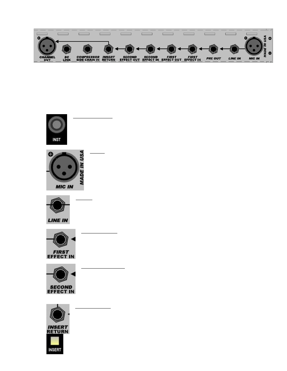
7.0 Rear Panel Interface
The rear panel of The Channel Strip provides a comprehensive package of interfacing options.
With the exception of the microphone and instrument inputs, all audio inputs and outputs are balanced, low
impedance +4dBu line level connections. All ¼” connectors are tip, ring, sleeve phone jacks.
7.1 Audio Path Inputs
The Channel Strip provides multiple audio inputs at various points in the audio path:
INST (Instrument): Instrument level input to the 512C Preamp (front panel)
•
¼” tip, sleeve jack
•
-10dBu
•
Unbalanced, high-impedance instrument input
MIC IN: microphone input to the 512C Preamp
•
Female XLR
•
Balanced, low-impedance input
LINE IN: Line level input to the 512C Preamp
•
¼” tip, ring, sleeve jack
•
+4dBu
•
Balanced, low-impedance input
INSERT RETURN: The signal present at this jack will replace the input to the 325
Line-Driver when the INSERT switch is engaged
•
The output section is normally fed from the SECOND EFFECT OUT
•
Engaging the INSERT switch will break the normal from the SECOND
EFFECT OUT
•
¼” tip, ring, sleeve jack
•
+4dBu
•
Balanced, low-impedance input
SECOND EFFECT IN: Line level input to the second signal processor in audio
path
•
Fed from the FIRST EFFECT OUT
•
Inserted signal will break the normal from the FIRST EFFECT OUT
•
Switching ¼” tip, ring, sleeve jack
•
+4dBu
•
Balanced, low-impedance input
FIRST EFFECT IN: Line level input to the first signal processor in audio path
•
Fed from the 512C Preamp output (PRE OUT)
•
Inserted signal will break the normal from the 512C Preamp output
•
Switching ¼” tip, ring, sleeve jack
•
+4dBu
•
Balanced, low-impedance input
27