2 compressor post equalizer, 3 compressor bypass, 4 compressor side chain – API Audio The Channel Strip User Manual
Page 19: 4 dc link
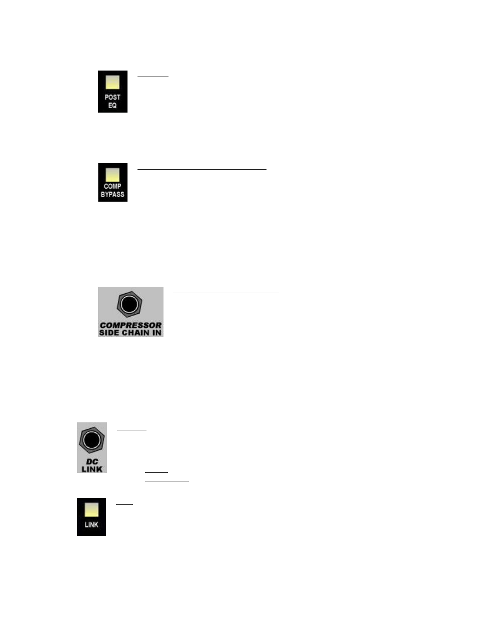
4.3.2 Compressor Post Equalizer
When the POST EQ switch is engaged, the 527 Compressor receives the output of the 550A
Equalizer and is interfaced via the SECOND EFFECT jacks on the rear panel.
POST EQ: Moves the 527 Compressor to post the 550A Equalizer in the audio path
•
527 Compressor will interface via the SECOND EFFECT jacks on the rear panel
•
550A Equalizer will interface via the FIRST EFFECT jacks on the rear panel
•
Illuminates when engaged
4.3.3 Compressor Bypass
When the COMP BYPASS switch is engaged, the 527 Compressor is completely removed from the
audio path via a hard relay-based bypass.
COMP BYPASS (Compressor Bypass): Completely removes the 527 Compressor from
the audio path
•
Relay hard bypass
•
Illuminates when engaged
4.3.4 Compressor Side Chain
The 527 Compressor Side Chain (detector path) is accessible via a balanced ¼” input on the rear
panel.
When the compressor type is set to NEW, the 527 Compressor Side Chain is fed by a split of the
input to the compressor. The detection path signal can be replaced by an external source by
inserting a plug in the COMPRESSOR SIDE CHAIN IN jack on the rear panel.
COMPRESSOR SIDE CHAIN IN: Replaces the signal to compressor detector
path with the inserted signal
•
Only effective when compressor is set to NEW type
•
Balanced, low-impedance +4dBu line level input
•
Switching ¼” TRS jack
4.4 DC Link
The 527 Compressor in The Channel Strip can be linked with 527 Compressors in other units for stereo
and multichannel applications. When connected together and the LINK switches are engaged, the DC
control voltages from all units are summed together. This results in the same control changes being
applied to all compressors. While this is not a “Master/Slave” configuration, the Threshold,
Attack/Release Times, and Ratio of all units should be set to the same value to prevent one channel
from generating a disproportionate contribution to the summed control voltage.
DC LINK: Control voltage input/output jack for the 527 Compressor
•
Active only when LINK switch is engaged
All DC LINK cables are ¼” TRS phone plugs wired tip-to-tip, ring-to-ring, and sleeve-
to-sleeve
•
Stereo: Cable with a ¼” TRS on each end
•
Multichannel: Cable with multiple ¼” TRS plugs
LINK: Activates the DC control voltage summing with other units
•
Illuminates when engaged
18