3 output section routing, 1 insert, 4 325 output section block diagram – API Audio The Channel Strip User Manual
Page 27
6.3 Output Section Routing
The output section is the last stage in the audio path and provides the Insert, VU Meter, 325 Line-Driver,
and main CHANNEL OUTPUT XLR interface.
The 325 Line-Driver can be fed from two (2) sources:
•
SECOND EFFECT OUT: The signal present at the SECOND EFFECT OUT jack is normalled to the
325 Line-Driver input.
•
INSERT RETURN: The signal present at the INSERT RETURN jack will be routed to the 325 Line-
Driver input when the INSERT switch is engaged.
The output of the Second Effect (normally the 550A Equalizer) is sent to the input to the 325 Line-Driver,
as well as the SECOND EFFECT OUT jack on the rear panel. This signal can be replaced by the signal
present at the INSERT RETURN jack on the rear panel by engaging the INSERT switch.
6.3.1 Insert
Engaging the INSERT switch will route the signal present at the INSERT RETURN jack to the input
of the 325 Line-Driver. When the INSERT switch engaged, the signal flow will be as follows:
INSERT RETURN: Replaces the input to 325 Line-Driver when the INSERT switch is
engaged
•
Only active when INSERT switch is engaged
•
Balanced, low-impedance, +4dBu line level input
•
¼” tip-ring-sleeve jack
INSERT: Activates the INSERT RETURN input
•
Routes the signal present at the INSERT RETURN jack to the 325 Line-Driver
•
Replaces the Second Effect output as the input to the 325 Line-Driver
•
Illuminates when engaged
NOTE: Since the signal can be externalized at multiple points in the audio path, The Channel
Strip does not have a dedicated “insert send” output. PRE OUT, FIRST EFFECT OUT, and
SECOND EFFECT OUT are intended to be used as “insert sends” as needed.
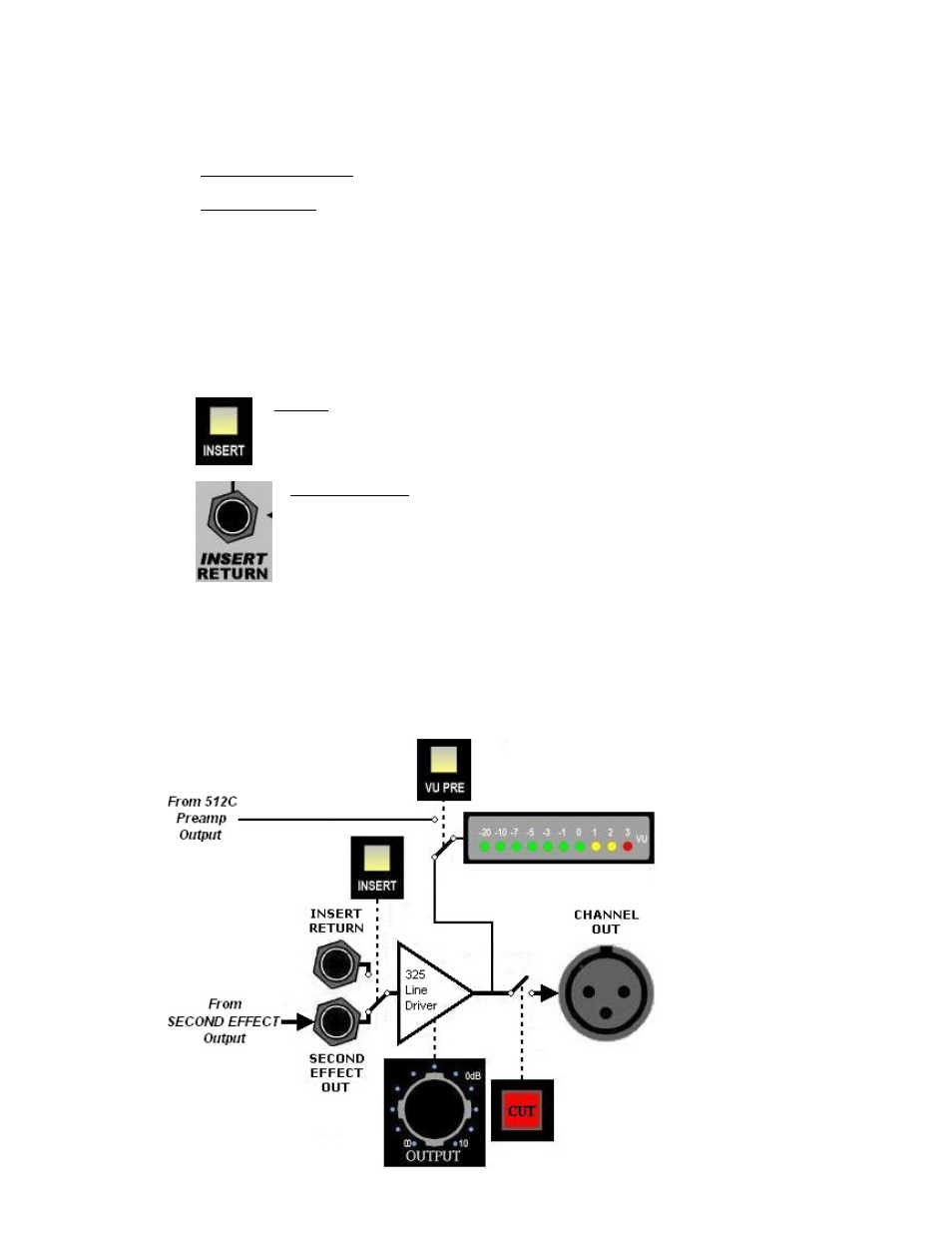
6.4 325 Output Section Block Diagram
The block diagram below illustrates signal flow through the 325 output section of The Channel Strip with
no switches engaged.
26