7 gain reduction meter, 3 compressor routing, 1 compressor pre equalizer (default signal flow) – API Audio The Channel Strip User Manual
Page 18
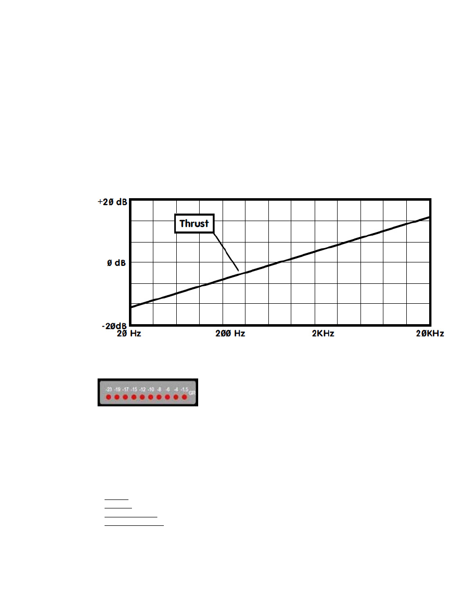
The patented THRUST® circuit has been used for many years in the famed API 2500 Stereo
Compressor, ATI Paragon and Paragon II consoles, as well as the Pro-6 Input Strip. This circuit
places a filter in front of the RMS detector with a slope of 10dB per decade (-3dB/8va), which is
the inverse of the pink noise energy curve. In acoustics, the pink noise curve is used to equalize
energy vs. frequency over the audio spectrum, as sound requires more low frequency energy than
high frequency energy to sound correct to your ear. In Hi-fi equipment, a “LOUDNESS” contour is
used to equalize the music at lower levels so it sounds correct. Even with this curve, there is still a
substantial amount of low frequency information compared to high frequency information in the
audio signal path. When that signal is fed into the RMS detector, the detector will process the
signal into a DC control voltage based upon the those louder low frequencies, resulting in a control
voltage that favors the low frequencies of the signal, causing pumping and a loss of punch.
Sometimes, this is not desirable. By engaging the THRUST® switch, this inverse filter is placed in
front of the RMS detector, evening out the energy by lowering the energy in the low frequencies
and increasing the energy in the high frequencies, so each octave has the same energy instead of
each octave having half the energy as the one lower. This creates a unique compression effect
that still reduces the overall gain, but the sound is much more punchy and the signal actually
sounds less compressed.
THRUST® filter response
4.2.7 Gain Reduction Meter
A gain reduction (GR) meter is provided to indicate the amount of compression being applied.
When no gain reduction is being applied, all LED’s are lit on the
Gain Reduction meter (GR). When compression occurs, the
corresponding LED’s extinguish to indicate the amount of gain
reduction. The following gain reduction increments are provided:
•
-1.5
dB
•
-4 dB
•
-6 dB
•
-8 dB
•
-10 dB
•
-12 dB
•
-15 dB
•
-17 dB
•
-19 dB
•
-23 dB
4.3 Compressor Routing
There are four (4) routing options for 527 Compressor:
•
Pre EQ: The 527 Compressor is located after the preamp and before the EQ (default signal flow)
•
Post EQ: The 527 Compressor is located after the EQ and before the output section
•
Hard Bypassed: The 527 Compressor is removed completely from the audio path
•
Side Chain Input: An external signal can replace the normal detector path input
4.3.1 Compressor Pre Equalizer (Default Signal Flow)
In the default signal flow (no routing switches engaged), the 527 Compressor receives the output
of the 512C Preamp.
•
527 Compressor will interface via the FIRST EFFECT jacks on the rear panel
•
550A Equalizer will interface via the SECOND EFFECT jacks on the rear panel
17