3 equalizer bypass, 4 insert, 3 default signal flow block diagram – API Audio The Channel Strip User Manual
Page 6
2.2.3 Equalizer Bypass
Engaging the EQ BYPASS switch will completely remove the 550A Equalizer from the signal path
using a relay-based hard bypass. When the COMP BYPASS switch is engaged, the signal flow will
be as follows:
512C Preamp -----> 527 Compressor -----> Insert -----> Output
EQ BYPASS: Removes the 550A Equalizer from the signal flow
•
550A Equalizer will not be accessible via rear panel interface jacks
•
Illuminates when engaged
IMPORTANT NOTE: The 550A Equalizer has an “IN” switch that must be engaged in order for the
equalizer to affect the signal when the EQ BYPASS switch is not engaged.
2.2.4 Insert
Engaging the INSERT switch will route the signal present at the INSERT RETURN jack to the input
of the 325 Line-Driver. When the INSERT switch is engaged, the signal flow will be as follows:
Insert -----> Output
INSERT: Routes the signal present at the INSERT RETURN jack to the 325 Line-Driver
input
•
Replaces the Second Effect output as the input to the 325 Line-Driver
•
Illuminates when engaged
NOTE: Since the signal can be externalized at multiple points in the audio path, The Channel
Strip does not have a dedicated “insert send” output. PRE OUT, FIRST EFFECT OUT, and
SECOND EFFECT OUT are intended to be used as “insert sends” as needed.
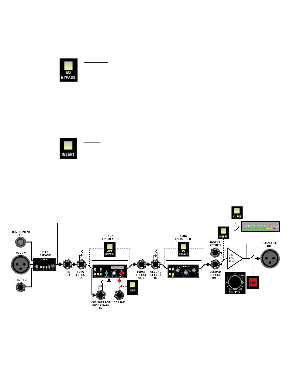
2.3 Default Signal Flow Block Diagram
The block diagram below illustrates The Channel Strip signal flow with no switches engaged except the
CUT button. This is the “default” signal flow through the unit.
5