2 asynchronous receiver transmitter, Figure 8-5, Telecom clock block diagram – Artesyn ATCA-8310 Installation and Use (May 2014) User Manual
Page 353: Cpld and fpga
Advertising
CPLD and FPGA
ATCA-8310 Installation and Use (6806800M72E)
353
8.2.3.2
Asynchronous Receiver Transmitter
Glue FPGA incorporates two Texas Instruments-compatible TL16C550C asynchronous
communications elements (COM 1 and COM 2) with Auto-Flow control. These UART units may
be mapped via Super IO Module.
For details on the address and interrupt map of the UART units via Super IO see
.
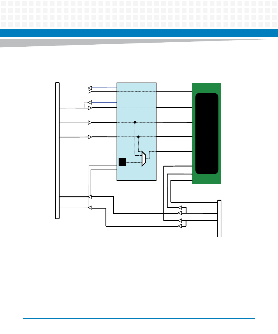
Figure 8-5
Telecom Clock Block diagram
CLK2A
CLK2B
CLK1A
CLK1B
ACS
8520B
Glue Logic FPGA
SYNC_2
CLK3A
CLK3B
REFCLK1
REFCLK2
EN_CLK3
EN_CLK3
I9
I10
Sync2K
I8
I7
I13
I12
I14 (T3
BITS)
6.48MHz
Advertising
This manual is related to the following products: