Beisler 1220-4 User Manual
Page 36
Operating manual Automatic single head serging unit 1220/4
Page 6-12
© Beisler GmbH, Hösbach
6.3.3.4
Page -10: Inputs and outputs
Inputs a switches and keys and are named ‘M1’ ... ‘M6’. Outputs are
all available magnet valves and are named ‘F1’ ... ‘F7’.
The programmin of an input/output is done in three steps:
1. Switch on or off.
2. Set start mode.
3. Set time values.
The inputs and outputs are occupied as follows:
I/O
Valve description
Connector
Y0
Lift sewing foot
A-1
F1
Y2
Table blowing
A-3
F2
Y3
Contour guiding
A-5
F3
Y13
Sucking nozzle
A-5
F4
Y4
Contour roll
A-7
F5
Y5
Kett-up
A-9
F6
Y6
Holding stamp
A-11
F7
Y7
Stacker impulse
A-13
M1
Reset key below the operation device
Pin 2-4
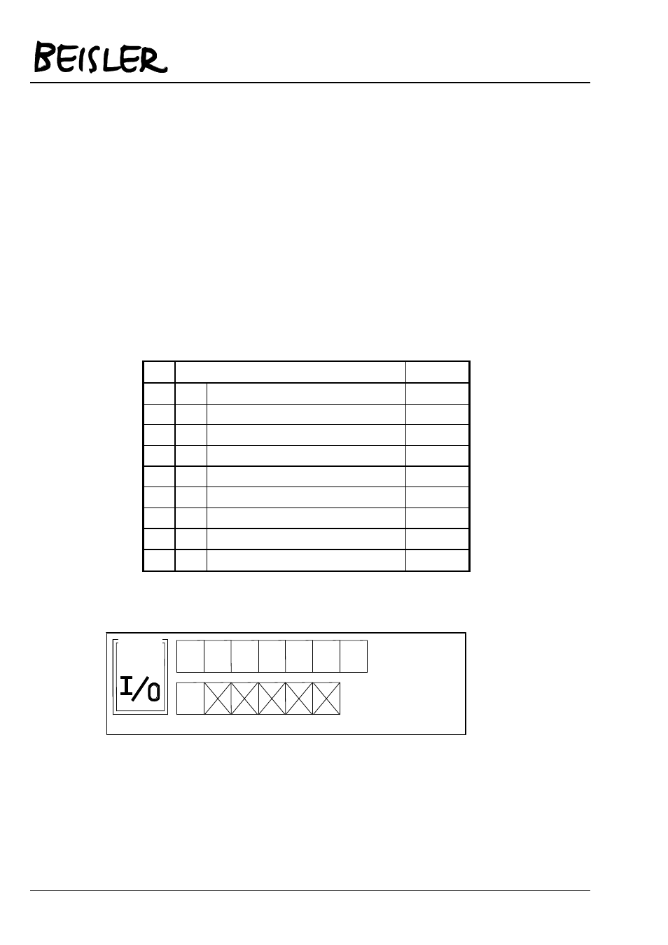
After you have selected setup page -10, the following will be
displayed:
M6
M5
M4
M3
M2
M1
F7
F6
F5
F4
F3
F2
F1
SETUP
-10