Comtech EF Data CRS-500 User Manual
Page 207
CRS-500 1:N Redundancy System
Revision 2
Appendix B
MN-CRS500
B–9
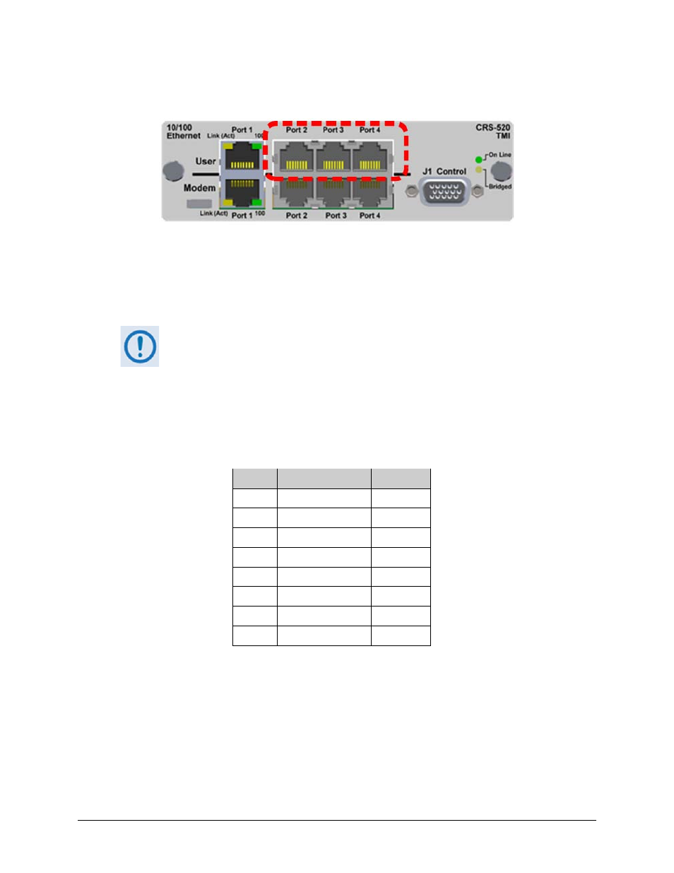
B.3.4 CRS-520 TMI – 10/100 Ethernet Connectors (RJ-45F)
The CRS-520 TMI provides four standard RJ-45F User Interface ports, operating at 10/100 Mbps,
half and full duplex, auto-negotiating for Ethernet Router Modes.
Table B-7 indicates the typical pinout for each of these connectors (10/100 Ethernet User “Port
1” through “Port 4”).
User Port 1 is reserved for use as the CRS-500 Ethernet System Communication
connection between the CRS-500 and the modems.
To avoid Ethernet Networking loops, CDM-625s operating in IP Packet Processor
Router Mode use only a single port of the CDM-625’s remaining available ports
(i.e., “Port 2” OR “Port 3” OR “Port 4”) to convey traffic data for each modem at
any given time.
Table B-7. 10/100 Ethernet Connector Pinout (Typical)
Pin #
Signal Function
Direction
1
Tx+
Tx only
2
Tx-
Tx only
3
Rx+
Rx only
4
N/C
–
5
N/C
–
6
Rx-
Rx only
7
N/C
–
8
N/C
–