2 csu rear panel – Comtech EF Data CRS-500 User Manual
Page 33
Advertising
CRS-500 1:N Redundancy System
Revision 2
Introduction
MN-CRS500
1–7
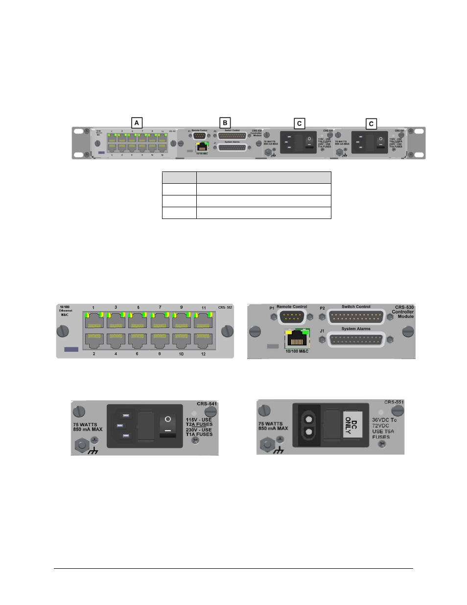
1.3.1.2 CSU Rear Panel
The CRS-500 power supplies and controller modules are located on the CSU rear panel (Figure
Feature Description
A
CRS-512 Ethernet M&C Interface
B
CRS-530 System Controller Module
C
Standard CRS-541 AC Power Supply
Figure 1-5. CRS-500 CSU Rear Panel Configuration Example
1.3.1.2.1
CSU Rear Panel System Controller, M&C, and Power
Supply Modules
DB-9M
DB-25M
RJ-45
HD-44 F
Figure 1-6. CRS-512 Ethernet M&C Module
Figure 1-7. CRS-530 System Controller Module
Figure 1-8. CRS-541 AC Power Supply
Figure 1-9. CRS-551 DC Power Supply (Optional)
Advertising