4 modem 9 / backup 2 configuration, 1 programming steps – Comtech EF Data RCS20 User Manual
Page 44
RCS20 M:N Redundancy Switch
Revision 15
User Interfaces
MN-RCS20 and CD-RCS20
4–10
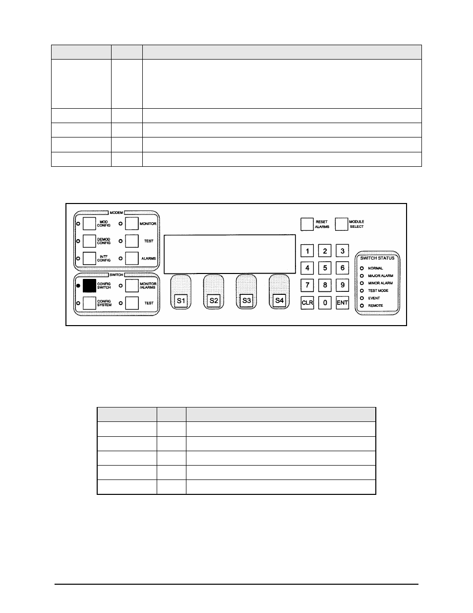
Key
Label
Function
S1
START
Press to begin the test. As each modem is being tested, the screen will indicate
astericks (**) at that location in the ACTIVE row. As the astericks move across the
screen, a ‘Y’ or N will appear indicating if the modulator and/or demodulator has a valid
connection.
S2
---
N/A
S3
---
N/A
S4
NEXT
Press to cycle to the next screen.
Numeric Keypad ---
N/A
4.3.1.4 MODEM 9 / BACKUP 2 CONFIGURATION
This screen allows the user to select the mode operation for Channel 9. The Channel 9 Modem can
operate as a prime or backup.
4.3.1.4.1 Programming steps:
1. Press <MODE> to cycle to the MODEM 9 / BACKUP 2 MODE Subscreen.
Key
Label
Function
S1
MODE Press to go the MODEM 9 / BACKUP 2 MODE Subscreen.
S2
---
N/A
S3
---
N/A
S4
NEXT Press to cycle to the next screen.
Numeric Keypad ---
N/A
MODEM 9 / <BACKUP> 2 CONFIGURATION
MODEM9 MODE : BACKUP
MODE NEXT