Flowserve QLQ Vertical Worthington User Manual
Page 16
QLQ, QLQC USER INSTRUCTIONS ENGLISH 87900027 – 06/14
Page 16 of 61
The typical nomenclature above is the general guide
to the QLQ configuration description. Identify the
actual pump size and serial number from the pump
nameplate. The driver will have a separate nameplate
attached it.
3.3 Design of major parts
3.3.1 Case assembly
Case assembly is designed to operate completely
submerged in the liquid. It consists of suction bells,
first and additional stages bowls, impellers and pump
shaft.
The suction bells serve as the input- ports to the first
stage impeller. Internal vanes support the housing of
the suction bell bearing.
The first stage casing is made of lower and upper
bell-mouth with bearing, double volute and discharge
branches with bearing. Twin volute is made efficiently
to convert to pressure the velocity added to the liquid
by the impeller.
Additional stage casings are diffuser type.
3.3.2 Impellers
QLQs are supplied with enclosed, double suction fist
stage impeller types, while additional stages impellers
are single suction. Impellers are low, medium and
high capacity type designed for maximum coverage
of all QLQ applications. Impellers are cast and
machined to match each order and to provide
required surface finish to achieve hydraulic
characteristics. Impellers are dynamically balanced
and held in position on the shaft by key and locking
nut.
3.3.3 Column assembly
The column assembly consists of column pipe, which
connects the bowl assembly to the discharge head
and carries the pumped fluid to the discharge head.
Houses and supports the shaft and may contain
bearings. Typical column assemblies are flanged, with
integrated bearing support.
The column supports shaft assembly, that is either
a) Open lineshaft construction utilizing the fluid being
pumped to lubricate the lineshaft bearings.
or
b) Enclosed lineshaft construction has an enclosing
tube around the lineshaft and utilizes oil or other
clean fluid to lubricate the lineshaft bearings.
The shafts are key coupled with thrust stud design or
clamp ring design.
The column shaft is usually divided in more sections
to facilitate the assembly during installation and
maintenance.
See sectional drawings supplied with the pump for
exact column assembly details as per the order. The
size and configuration vary depending upon the
specific order requirements and application criteria
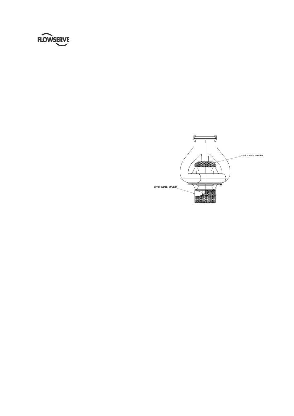
3.3.4 Suction strainers
Wet Pit (sump) QLQs can also be fitted with strainers
to prevent foreign particles from entering the pump.
The type of strainers and the mesh size depends on
the application. An example is shown below.
Strainers are usually fastened directly to the suction
bells .
3.3.5 Suction Can
Suction can is designed to allow the impeller to have
the proper level of NPSH to run properly, when the
available NPSH is insufficient at ground level.
It's connected with the Suction Head, and can be
directly installed on the foundations or through a
separate foundation plate,
According to the specification, it can be designed to
withstand the maximum Suction Pressure or to
withstand the Maximum Allowable Working Pressure.
Consult the dedicated pump document for more
details on it.
3.3.6 Discharge Head Assembly
The discharge head supports the driver and bowl
assembly as well as supplying a discharge connection
in most cases. A shaft sealing arrangement is located
in the discharge head to seal the shaft at its exit from
the liquid chamber. The shaft seal will usually be
either a mechanical seal assembly or packing seal
with an open lineshaft or a tube-packing box with an
enclosed lineshaft.
If the pump is required to have its own thrust bearing,
it is installed in the discharge head has the pump
thrust bearing integrated.
The different types of discharge heads can be
summarized in two types.