Flowserve QLQ Vertical Worthington User Manual
Page 29
QLQ, QLQC USER INSTRUCTIONS ENGLISH 87900027 – 06/14
Page 29 of 61
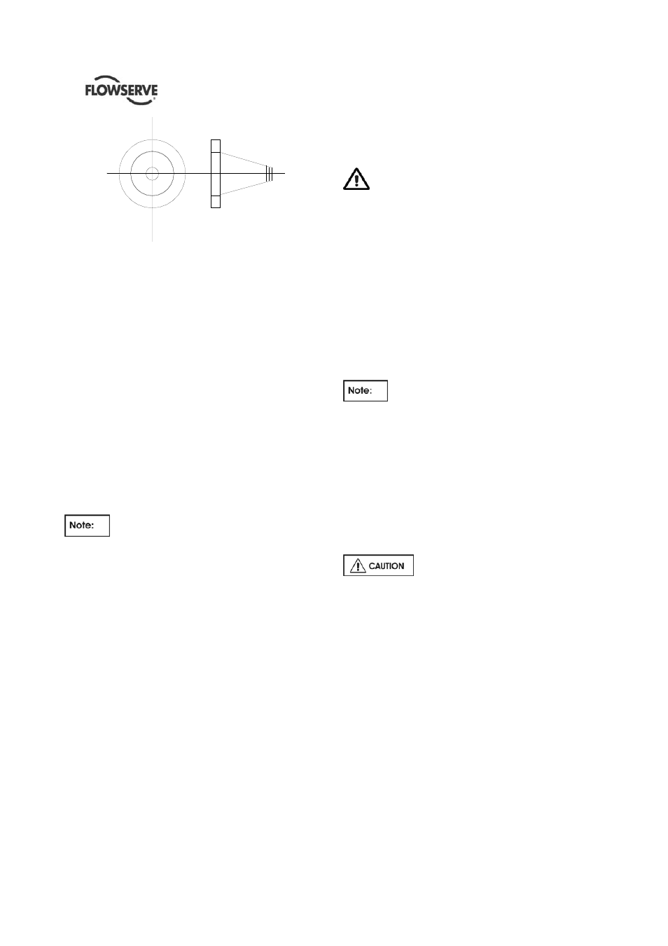
Figure 4.14
Cone Type Strainer
The Flowserve recommendation for suction strainers
consists of a conical shaped steel plate. The plate
has 1.6 mm (1/16 in.) perforations and is of sufficient
size and thickness for the required flow. See Figure
above.
Other type of strainers may be used as long as they
conform to the requirements stated above.
Pressure gauges should be installed on both sides of
the screen so that the pressure drop across the
screen can be measured.
When the unit is being started, the gauges on each
side of the screen should be carefully watched. An
increase in the differential pressure between the two
gauges indicates that the screen is becoming clogged
with dirt and scale. At this point, the pump should be
shut down, and the screen cleaned and/or replaced.
A spool piece should be installed in
suction line so that the suction strainer may be
installed and removed with a pressure gauge
between the strainer and pump.
4.6.3 Discharge piping
a)
Install a check valve and a gate valve in the
discharge pipe of the pump. When the pump is
stopped, the check valve will protect the pump
against excessive pressure and will prevent the
pump from running backward. The check valve
should be installed between the gate valve and
the pump nozzle in order to permit its inspection.
Never throttle pump on suction side and never
place a valve directly on the pump inlet nozzle.
b) Pipework reducers should have a maximum total
angle of divergence of 15 degrees.
Take into account the available NPSH that must be
higher than the required NPSH of the pump.
4.6.4 Auxiliary piping
4.6.4.1 Drains
Normal pump leaks and gland leakage are to be
drained through a separate piping arrangement or
back into the suction/sump.
Ensure proper drain in case of hazardous,
flammable or toxic pumped fluid.
4.6.4.2 Pumps fitted with gland packing
The pump is shipped without packing in the stuffing
box. A complete set of packing is shipped in a
separate box attached to the pump crate.
Properly packed stuffing box is a must for efficient
pump operation. Proceed as follow:
a) Clean out the stuffing box.
b) Install three rings of packing at the bottom of the
stuffing box.
c) Insert the lantern ring.
d) Continue adding the required number of packing
rings, in accordance with cross section drawing
Install one ring of stuffing box packing in the
box at a time, making sure it is properly seated.
e) Stagger the joints of succeeding rings. When the
last ring is in place, assemble the gland and pull
up the nuts evenly until snug. Then back off the
nuts and re-tighten finger tight.
The stream of leakage following pump startup
can be controlled by taking up the gland nuts. It is
suggested that this is done slowly, one flat at a
time until satisfactorily leakage or lubrication has
been obtained.
Packing gland must never be
tightened to the point where leakage from the packing
is stopped. A small amount of leakage is required for
lubrication of the packing. Tightening the packing until
stopping the leakage flow from the packing will result
in burning of the packing, scored shaft sleeve and
possible rotor seizure.
4.6.4.3 Pumps fitted with mechanical seals
QLQs pumps can be equipped with single or double
cartridge mechanical seal.
In relation to the different condition of services, type
of fluid and pressures, different seal flushing plans
can be provided.
Refer to the dedicated General Arrangement drawing
included in the Instruction Manual Book to see the
type of flushing plan installed.
Against the dedicated documents, check that the
flushing plan is correctly assembled and secured.