Flowserve QLQ Vertical Worthington User Manual
Page 17
QLQ, QLQC USER INSTRUCTIONS ENGLISH 87900027 – 06/14
Page 17 of 61
3.3.6.1 Head for Wet pit (sump) pumps
The head has the suction nozzle and the thrust
bearing (if installed in the pump) integrated.
The head is fixed to the ground by means of a
foundation plate or by foundation beams on which the
head is placed.
3.3.6.2 Head for double casing (can) pumps
The head has the suction nozzle, the discharge
nozzle, the thrust bearing (if installed on the pump)
integrated. The head is connected to the suction
barrel (can) through a flange; the head can have
provisions to be fixed directly to the ground or to be
fixed on a separate foundation plate.
For special layouts the suction nozzle can be placed
below the mounting level (refer to the dedicated
General Arrangement drawing for reference).
3.3.7 Motor Stool
The motor stool is a fabricated steel structure
designed to maintain the proper alignment between
pump and electric motor.
It can be integrated with the pump head or it can be a
separate piece fixed upon the suction head.
3.3.8 Drivers
A variety of drivers may be used, however, electric
motors are most common. For the purposes of this
manual, all types of drivers can be grouped into two
categories.
a) Hollow shaft drivers: where the head shaft extends
through a tube in the center of the rotor and is
connected to the driver by a clutch assembly at the top
of the driver.
b) Solid shaft drivers: where the rotor shaft is solid
and projects below the driver-mounting base. This type
driver requires an adjustable coupling for connecting to
the pump.
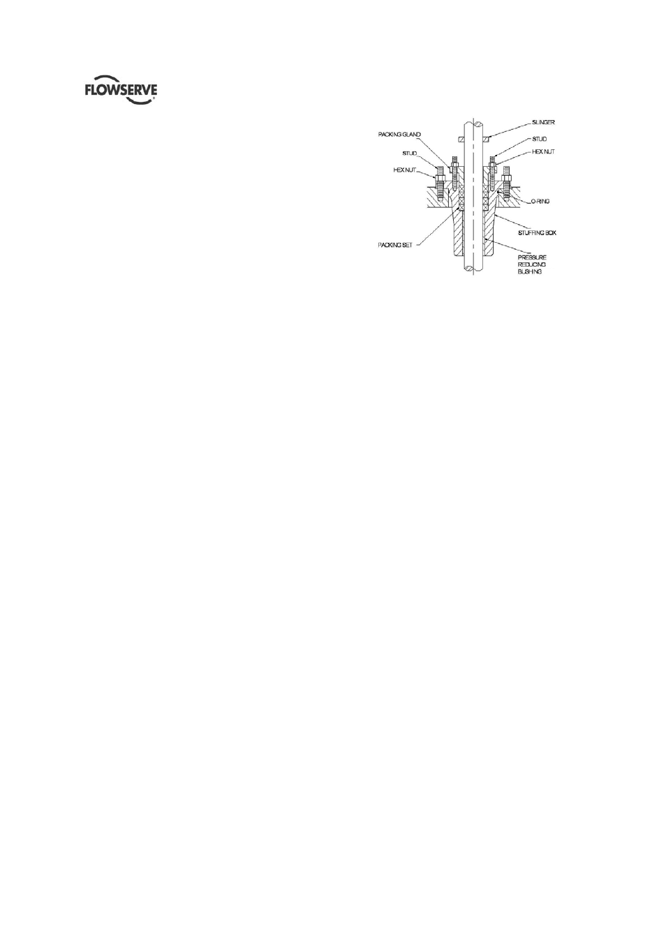
3.3.9 Stuffing box
QLQs are fitted with stuffing boxes which are
adequate for the pump working pressure. Stuffing
boxes may fit a mechanical or packing seal.
3.3.10 Mechanical shaft seal
QLQs can be fitted with single or double mechanical
seal. Depending on the services specified, the
mechanical seal has different plan to provide the
proper flushing to the faces trough appropriate piping
either installed on the pump or to be provided and
mounted when the pump is installed.
3.3.11 Thrust Bearing (if installed)
The pump shall be equipped with a thrust bearing
installed in the suction head (alternatively, the thrust
bearing of the driver can be designed to withstand the
thrusts of the pump).
The thrust bearing is designed to withstand the axial
loads (static weights of rotors and hydraulic loads)
occurring throughout the pump operating range.
The thrust bearings can be ball type, roller type or
tilting pad.
The bearings are housed in a fabricated steel support
directly mounted on the upper side of the discharge
head.
Lubrication of the thrust bearings is provided by oil
bath.
As standard option, an oil sight glass in installed
outside the bearing house to check oil level and
refilling.
3.3.12 Flexible coupling with spacer (if installed)
If the pump is equipped with thrust bearing, the pump
shaft is joined to the driver shaft with a flexible
coupling with spacer.
The flexible coupling allow the transmission of the
torque to the pump, but not the axial loads.
3.3.13 Rigid Coupling with spacer between
mechanical seal and bearing support (if installed)
If the pump is equipped with mechanical seal and
thrust bearing, a rigid coupling with spacer is placed
between the thrust bearing and the mechanical seal.
By the removal of the coupling hub and the spacer
only the removal of the mechanical seal is without the