Flowserve QLQ Vertical Worthington User Manual
Page 35
QLQ, QLQC USER INSTRUCTIONS ENGLISH 87900027 – 06/14
Page 35 of 61
a) With the pump completely installed, proceed
installing the hubs of the rigid coupling (thrust
bearing side and pump side).
b) Lift the pump rotor till its upper position and
record the vertical distance from a reference
point.
c) Release the rotor to its lower position, and record
again the position form the same reference point
d) The pump rotor shall have an axial run of
5÷10mm (0.2÷0.4 inches). If the recorded run is
different form this range, re- check the installation
and pump assembly.
e) By rotating the screwed collar installed on the
pump coupling hub, position the rotor at the
middle of the run (half the value from the top and
the bottom measured).
f) Proceed aligning the hubs according to section
5.3.2.
The position of the regulating nut is located
on the rigid coupling. If the rigid coupling is not
installed, the impeller adjustment shall be done
through the regulating nut placed at the top of the
bearing house. Refer to the dedicated Cross
Sectional drawing supplied with the IOM book to
identify where the adjusting impeller nut is located.
5.4.2 Impeller adjustment for a hollow shaft
driver
Impeller adjustment when using hollow shaft drivers is
as follows. The driver canopy will have to be removed
before beginning.
a) Install headshaft if not already in place.
b) Install driver clutch in accordance with the driver
instruction manual and bolt into place.
c) Check shaft position. Lower shaft until there is a
definite feel of metal contacting metal. This
indicates the impellers are "on bottom" and in the
correct starting position for impeller adjustment.
d) Thread headshaft nut down (right hand threads)
except 43 mm (1.7 in.) and larger sizes that are
having left hand threads, until impellers are just
raised off their seat and the shaft will rotate freely.
e) Check a separate document that is supplied with
the pump that provides recommended impeller
setting and running clearance information.
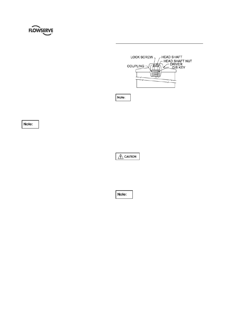
Detail showing head shaft and lock screw arrangement
If at any time during the life of this pump the
pumping conditions or total pump length changes,
contact the factory for recalculation of the impeller
setting.
f) Tighten the adjusting nut to match impeller setting
recommended by Flowserve.
g) Using the cap screw provided, bolt the headshaft
nut down & lock using lock screw to the motor
coupling. See the details of head shaft and lock
screw arrangement under item (h) below.
Always lock headshaft nut by
tightening the lock screw before starting driver.
Failure to do so could result in damage to the pump
and driver.
h) If a mechanical seal is used, adjust the
mechanical seal at this time.
Shafts elongate due to the hydraulic thrust
of the pump and the impellers must be compensated
for this elongation. Shaft elongation varies for each
model depending upon the size, shaft length, shaft
diameter, impeller weight, number of stages. Please
see the documentation supplied along with the pump
for exact impeller setting value matched for the
specific pump that you have purchased.