Flowserve QLQ Vertical Worthington User Manual
Page 26
QLQ, QLQC USER INSTRUCTIONS ENGLISH 87900027 – 06/14
Page 26 of 61
4.5 Initial alignment
4.5.1 Thermal expansion
The pump and motor will normally
have to be aligned at ambient temperature and
should be corrected to allow for thermal expansion at
operating temperature. In pump installations involving
high liquid temperatures, the unit should be run at the
actual operating temperature, shut down and the
alignment checked immediately.
4.5.2 Preparation before alignment
To ensure proper alignment the following items are
very important.
a) All machined mating surfaces (such as the
mating flanges of pump and motor) must be
clean and free of burrs and nicks.
b) Exterior strain must not be transmitted to the
pump. The most common cause of trouble is
forcing the piping to mate with the pump. It is
recommended that flexible connectors be installed
in the piping adjacent to the pump.
c) All threads should be checked for damage and
repaired if necessary. Lubricate all threaded
connections with a suitable thread lubricant (an
anti-galling compound).
4.5.3 Alignment methods
Ensure pump and driver are isolated
electrically and the half couplings are disconnected.
The alignment MUST be checked.
Although the pump will have been aligned at the
factory it is most likely that this alignment will have
been disturbed during transportation or handling.
If necessary, align the motor to the pump, not the
pump to the motor.
The motor assembly has to be adjusted in
the horizontal direction to line up the driver and shaft
centers. Alignment screws are provided to lock the
motor assembly in its final aligned position.
See section 5.3.2.1 for final coupling alignment for
solid shaft.
Check the direction of pump rotation
before the coupling is fully connected. The power
supply to the driver to be connected only after the
final alignment is complete.
4.5.3.1 Shaft./Coupling alignment
Shaft alignment must be correct for
successful operation. Rapid wear, noise, vibration
and actual damage to the equipment may be
caused by shaft misalignment. The shafts must
be aligned within the limits given within this
section.
Adjustment to correct the alignment in one
direction may alter the alignment in another direction.
Always check in all directions after making any
adjustment.
Coupled equipment must be aligned to minimize
unnecessary stresses in shafts, bearings and
coupling. Flexible couplings will not compensate for
appreciable misalignment. Foundation settling,
thermal expansion or nozzle loads resulting in
baseplate/foundation deflection and vibration during
operation may require the full coupling misalignment
capability.
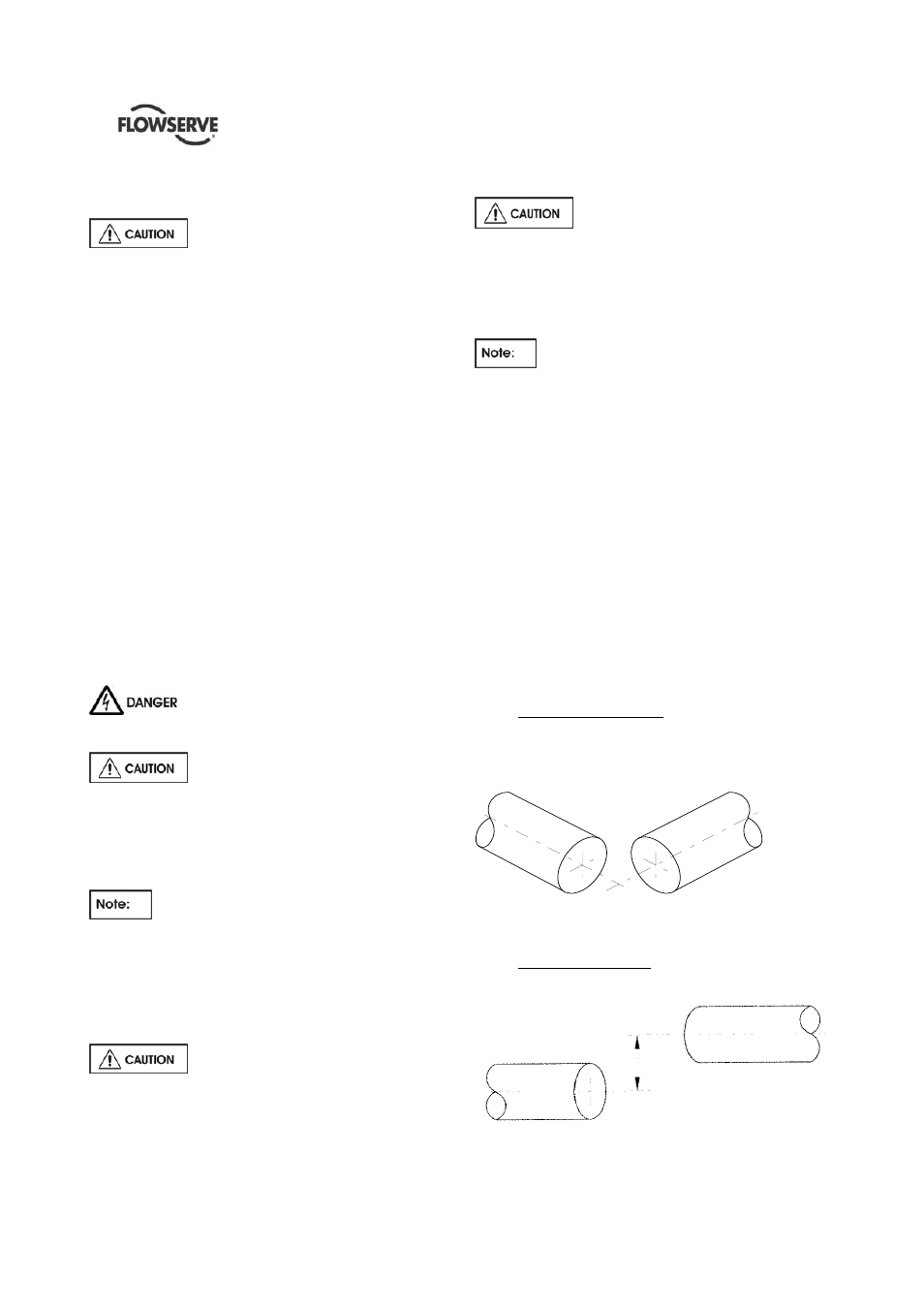
4.5.3.2 Types of misalignment
There are two types of shaft misalignment: angular
and offset. Therefore, two sets of measurements and
corrections are required. Both types of misalignment
can occur in horizontal and vertical planes and are
present in most applications.
a)
Angular misalignment
In angular misalignment, the center line of the shafts
intersect, but are not on the same axis.
Figure 4.9
b) Offset
misalignment
In offset misalignment, the shaft center lines are
parallel but do not intersect.
Figure 4.10 – offset misalignment