Flowserve QLQ Vertical Worthington User Manual
Page 23
QLQ, QLQC USER INSTRUCTIONS ENGLISH 87900027 – 06/14
Page 23 of 61
Check the packing slip to see if a guide bushing is
required, if so, determine if the bushing is already
mounted or not and proceed accordingly. Refer to
motor instruction manual.
j) Carefully install drive clutch on driver making sure
that it fits down properly.
k) Clean threads on top of head shaft and head shaft
nut. Lubricate male threads lightly. Install head
shaft.
l) Install gib key in clutch and shaft. This must be a
sliding fit and may require filing and dressing. Do
not force.
m) Thread adjusting nut down on shaft until it bears
against clutch. (Threads on 43 mm (1.68 in.) and
larger head shaft adjusting nuts are left-handed
and all others are right handed). Do not thread nut
further at this time. See impeller adjusting
instructions in section 5.3.
Figure 4.1
4.2 Part assemblies
Motors may be supplied separately from the pumps.
It is the responsibility of the installer to ensure that
the motor is assembled to the pump and aligned as
detailed in section 4.5. Discharge head column piping
and the pump assembly are supplied either
separately or as fully assembled depending upon the
pump size and weight. If the parts are shipped
separately, it is the customer’s responsibility to install
and align the pump with driver to the satisfaction of
Flowserve’s installation instructions.
4.3 Foundation
There are many methods of installing
pump units to their foundations. The correct method
depends on the size of the pump unit, its location and
noise vibration limitations. Non-compliance with the
provision of correct foundation and installation may
lead to failure of the pump and, as such, would be
outside the terms of the warranty.
The foundation should be sufficiently rigid and
substantial to prevent any pump vibration and to
permanently support the baseplate at all points.
The most satisfactory foundations are made of
reinforced concrete. These should be poured well in
advance of the installation to allow sufficient time for
drying and curing.
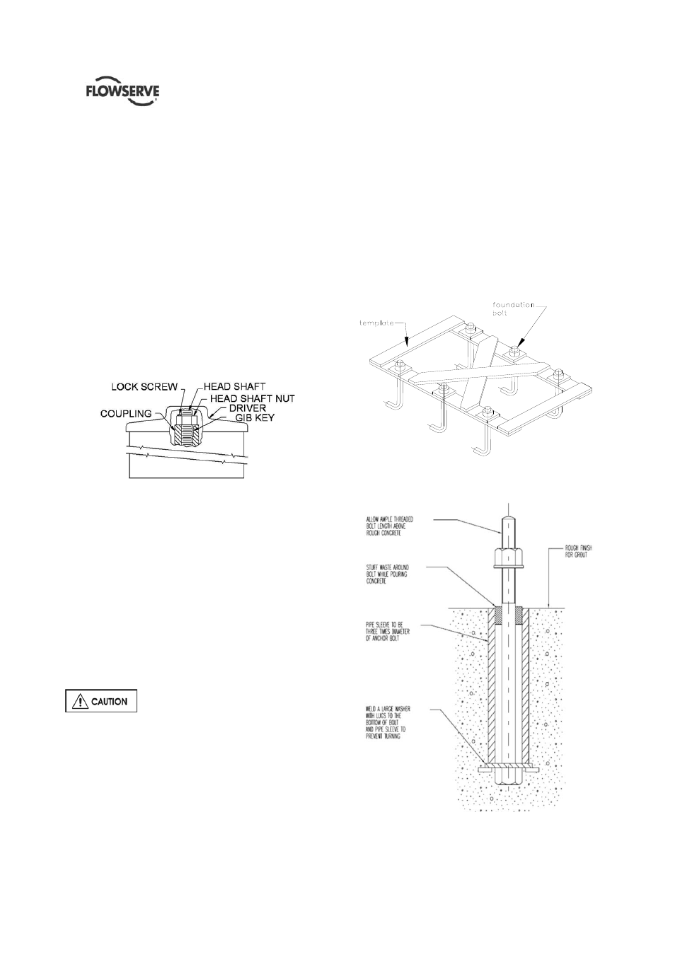
The General Arrangement Drawing (In Job’s User
Instruction) will furnish overall outline of pump
foundation plate, anchor bolt locations, size of bolts,
etc. in order to provide proper shape to the primary
concrete. Anchor bolts can be positioned or by a
special template (not supplied by FLOWSERVE see
figure 4.2) or by the foundation itself if proper pockets
have been provided in primary concrete.
Figure 4.2
Template for Hanging Foundation Bolts
Figure 4.3