6 setting impeller clearance, 7 disassembly – Flowserve QLQ Vertical Worthington User Manual
Page 45
QLQ, QLQC USER INSTRUCTIONS ENGLISH 87900027 – 06/14
Page 45 of 61
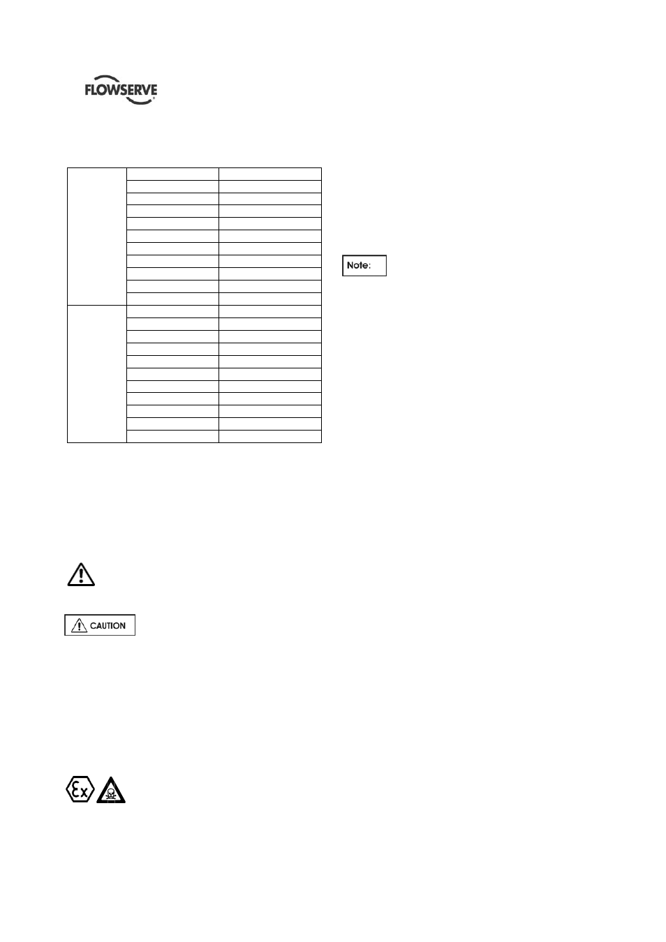
6.5.1 Pump main bolting and general application
bolting
Mate
rial: A193 Gr
B7
Nit
roni
c
50
Thread size (inch)
Torque Nm - (lbf ft.)
3/8" 23.5
(17.3)
1/2" 59
(43.5)
5/8" 118
(87)
3/4" 225.5
(166)
7/8" 363
(268)
1" 520
(383.5)
1.1/8" 696
(513.5)
1.1/4" 1049
(774)
1.3/8" 1304
(962)
1.1/2" 1638
(1208)
Mate
rial: A193 Gr
B8M
Thread size (inch)
Torque Nm - (lbf ft.)
3/8" 17.6
(13)
1/2" 44.5
(32.5)
5/8" 88.5
(65.3)
3/4" 167
(123)
7/8" 275
(203)
1" 392
(289)
1.1/8" 520
(383.5)
1.1/4" 785
(579)
1.3/8" 981
(723.5)
1.1/2" 1226
(904)
6.6 Setting impeller clearance
Please see section 5.4 for specific instructions on
impeller adjustment.
6.7 Disassembly
Refer to section 1.6, Safety, before
dismantling the pump.
Before dismantling the pump make sure that the
power supply is turned off. Pump controls are in
off position, locked and tagged.
Ensure genuine Flowserve replacement parts are
available on hand.
Refer to sectional drawings for part numbers and
identification.
Contact Flowserve for repair/disassembly/ rework
instructions as each order is different and are
made specific to the requirements.
Please take precaution during
disassembly that there is no risk of explosion due to
the nature of the materials/tools/equipment/method
used. Wherever chemical and hazardous materials
are involved, proper safety rules have to be followed
to prevent any dangers to human lives or livestock.
Contact Flowserve for guidance, or local regulatory
agency for specific safety information.
6.7.1 Pump dismantling instructions
See the dedicated Sectional Drawing referred to the
specific pump to identify the components and the
codes.
Care must be exercised in the dismantling
operation to prevent damages to internal parts of the
pump. Lay out all parts in the same order in which
they are removed for convenience at assembly
Protect all machined faces against metal-to-metal
contact and corrosion.
a) Switch off, lock and tag motor circuit breakers.
Disconnect all cables/wires and cooling water
pipe connections to the driver (if provided).
b) Switch off, isolate and tag all instrumentation and
monitoring equipment ( if installed).
c) Close pump suction valve. If discharge valve has
not already been closed, this must be done prior
to dismantling.
d) Close pump suction vent
e) Remove
pump
coupling
guards.
f) If the pump has a thrust bearing separate from
the driver, drain bearing house of oil and remove
the oiler.
g) Disconnect and remove all auxiliary piping lines.
h) Remove the coupling bolts between pump and
motor coupling hubs.
i)
Remove bolts that secure motor to motor stool.
j) Attach a sling to motor lifting eyes and lift motor
vertically until driver coupling clears motor stool.
k) Provide a suitable support and lower the motor
on it.
l) If the motor stool is not integrated with the
discharge head, loosen the bolts fixing the motor
stool to the discharge head, and remove it, if
there's no thrust bearing on it.
If the thrust bearing is placed on the motor stool,
remove the motor stool after the removal of the
thrust bearing.
m) Remove bolts and withdraw coupling spacer.
n) Remove pump coupling hub, using a puller
and/or applying heat if necessary. Remove the
coupling key.
o) If the pump is equipped with mechanical seal,
loosen mechanical seal drive collar set Screws.
Insert first locking tabs into shaft sleeve groove.
If the pump is equipped with packing seal, loose
seal packing.