Motor protection, Short circuit protection – Flowserve Byron Jackson Type M User Manual
Page 18
Byron Jackson Double Mechanical Seal Submersible Pumping Unit • 1042.293/9 • June
04
Page 18 of 68
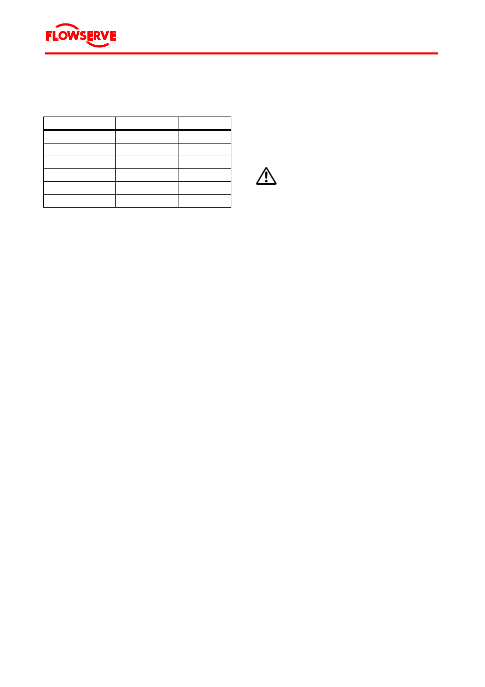
With variations in voltage, the motor characteristics
will, in general, vary as given in Table 2.
Voltage
110 %
90 %
Speed
Increase 1 %
Decrease 1.5 %
Efficiency (full load)
Increase 0.5 %
Decrease 1 %
Power factor (full load) Decrease 3 %
No change
Current (starting)
Increase 11 %
Decrease 11 %
Current (full load)
Decrease 8 %
Increase 11 %
Temperature
Decrease 2 %
Increase 5 %
Table 2
Motor characteristics at varying voltage
Rated or full load current refers to the amperage
drawn by the motor at nameplate output, frequency
and voltage at the motor terminals. The maximum
allowable current (except momentarily at start-up)
is 110 % of the rated value.
The voltage on all three phases should be evenly
balanced as closely as can be read on the usually
available commercial voltmeter, because the cur-
rent unbalance will be in the order of 6 to 10 times
the voltage unbalance. Running the motor with the
unbalanced voltage will lead to increased tempera-
ture and decreased motor life time, and therefore
must be avoided.
Poor voltage regulations of an engine-driven gen-
erator, if the power is derived from such a source,
can be very disadvantageous to the motor. Thus,
Flowserve assumes no responsibility for pumping
units operated on such equipment unless agreed
on in writing.
Also, because of the unpredictable characteristics
and past experiences associated with the use of
phase converters, Flowserve must void all guaran-
tees for applications that incorporate these devices
as a means of obtaining three phase power.
3.5.2 Motor
protection
To protect the motor against power overload, an
inverse time-lag overload relay must be provided,
sensitive to phase failure and which compensates
for temperature.
The over current relay for the switchgear and the
safety fuses can be adjusted or selected according
to Chapter 12.2 "Data sheet".
The adjustment of the motor protection switch
(thermally delayed over current relay) must be
done according to the value given in Chapter 12.2
"Data sheet".
The value given in Chapter 12.2 "Data sheet", is a
standard value for the operating point. If the actual
operational current in the operating point of the
pump bowl assembly lies under this given value,
the switch must be adjusted lower so that there is
effective protection and malfunctions can be indi-
cated in time.
DANGER
Do not set the motor protection ad-
justment higher than the highest per-
missible value given in Chapter 12.2
"Data sheet".
Do not test the perfect functioning of
a motor protection switch by inten-
tional single-phasing.
3.5.3
Short circuit protection
To prevent short circuiting of the power cable and
the motor, safety measures must be taken accord-
ing to local ordinances.
Guide values for the safety fuse sizes can be taken
from Chapter 12.2 "Data sheet".