Flowserve Byron Jackson Type M User Manual
Page 29
Byron Jackson Double Mechanical Seal Submersible Pumping Unit • 1042.293/9 • June
04
Page 29 of 68
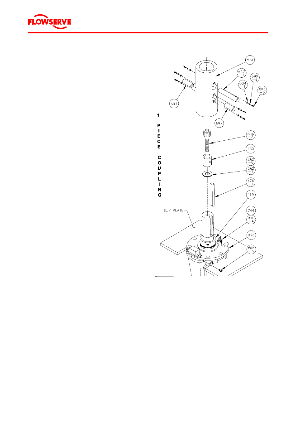
Variant B: One-piece coupling
1.
Clean the coupling (531) and shaft and lightly
oil both.
2. Identify the thrust button (130), thrust button
screw (806-2) and shaft adjusting shims
(262-6 and 262-7) as required. These pieces
are factory installed.
3. Insert key (676-1), round end down, in the
keyway.
4. Slip coupling (531) on shaft with keyways
aligned.
CAUTION Do not force the coupling.
If the coupling will not seat prop-
erly, again verify that shaft and
coupling are clean.
5. Install the coupling pins (697) into the cou-
pling holes and the thrust button.
The thrust button may need to be rotated to
align holes.
Install the coupling lock screws (806-6), flat
washers (004-1), and lock washers (690-6) to
secure the pins in the coupling.
6. Tighten the thrust button socket head screw
(806-2).
7. Rotate the motor shaft and coupling until the
pin holes on the coupling are pointed 90 °
from the power terminal shipping cap.
This aligns pin holes in coupling with adapter
bracket to allow pump coupling pin (697-1) to
be installed later. Also see Figure 12.
8.
Clean the motor flange face of any dirt or for-
eign matter. Verify that the balance line hole is
open and clear.
9. Cover the coupling (531) and shaft with a
clean cloth.
The coupling is now ready to receive the pump
bowl assembly.
Figure 12 Components for one-piece coupling