Install impeller, Install impeller, see – Flowserve Byron Jackson Type M User Manual
Page 32
Byron Jackson Double Mechanical Seal Submersible Pumping Unit • 1042.293/9 • June
04
Page 32 of 68
4.4.9 Install
impeller
NOTE Not all components or sub-
assemblies of a pumping unit are
necessarily supplied by Flowserve
or part of this delivery.
These user instructions apply only
to the components or sub-
assemblies supplied by Flowserve
in this delivery, see Chapter 12.1
"Scope of delivery".
Flowserve manufactures two impeller variants for
the Byron Jackson Double Mechanical Seal Motor:
•
Variant A: Closed impeller
•
Variant B: Open impeller
Both are described in the following. See Chapter
12.1 "Scope of delivery" to determine the coupling
delivered and follow the respective instructions.
Variant A: Closed impeller
1.
Scale from the face of the adapter bracket
(808) to the end of the pump shaft (167) with
the shaft down.
2. Remove adapter bracket (808) from bowl as-
sembly.
3. Install adapter bracket (808) on motor top
flange, using fasteners for motor shipping cap
(112-1).
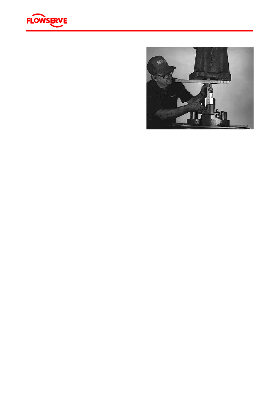
4. Scale from the face of the motor top case
(076) to the face of the shaft adjusting button
(130).
5. The distance recorded in step 1 should be
3.175 mm to 6.350 mm (1/8" to 1/4") less than
that of step 4.
Figure 16 Verify end float
Variant B: Open impeller
1. Remove adapter bracket (808) from bowl as-
sembly.
2. Install adapter bracket (808) on motor top
flange, using fasteners from motor shipping
cap (112-1).
3.
Remove the pump half coupling (530) or one-
piece coupling (531).
4. Provide four pieces of shim stock, each
(50.8 mm x 50.8 mm x 0.508 mm (2" x 2" x
0.020") thick, and place each shim 90 degrees
apart on the face of the adapter bracket.
5. Lower the pump bowl assembly into the
adapter bracket (808) to rest on the shims.
6. Put a feeler gauge through the plug opening
in the adapter bracket (808) and check the
gap from shaft adjusting button (130) to pump
shaft (167).
7.
If gap, step 6, is less than 0.0381 mm (0.015")
or more than 0.4572 mm (0.018"), the shims
beneath the shaft button (130) must be
changed.
8.
Reinstall the pump half coupling (530) or one-
piece coupling (531).