Install pump bowl assembly, Install pump bowl assembly, see cha – Flowserve Byron Jackson Type M User Manual
Page 30
Byron Jackson Double Mechanical Seal Submersible Pumping Unit • 1042.293/9 • June
04
Page 30 of 68
4.4.8
Install pump bowl assembly
NOTE Not all components or sub-
assemblies of a pumping unit are
necessarily supplied by Flowserve
or part of this delivery.
These user instructions apply only
to the components or sub-
assemblies supplied by Flowserve
in this delivery, see Chapter 12.1
"Scope of delivery".
Lift pump bowl assembly
Never step under floating load.
Watch for and avoid overhead ob-
structions including power lines.
NOTE
The following description refers to
pumps without auxiliary carriers.
Should the pump be delivered on an
auxiliary carrier, refer to the pump
manual for lifting instructions.
To transport the pump bowl assembly to the well
site see Chapter 2.2.4 "Transport of the pump bowl
assembly", Page 11.
1. Connect the pump to two lifting lines of a
portable crane.
The attachment points may vary according to
pump type and local requirements.
2. Carefully lift the pump to a vertical position
over the well head.
Install pump bowl assembly
The riser pipes are connected among each other
by
•
threads or
•
flanges.
The motor hangs in the well on the U-plate.
1. Disassemble discharge housing or non-return
valve from the pump bowl assembly.
2. Install
the
discharge housing or non-return
valve in the short section of riser pipe.
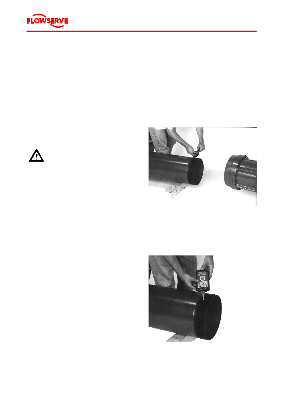
Additional information for threaded riser pipes:
a.
Clean the mating pipe threads of the pipe
and the case or flange as shown in
Figure 13.
Figure 13 Cleaning riser pipe threads
b. Apply thread locking fluid, e. g. Loctite
242 or DELO 5249/5349 or equivalent, to
the threads as shown in Figure 14.
Figure 14 Applying thread locking fluid