Fluke Biomedical DALE601 User Manual
Page 18
DALE601/601E
Operators Manual
1-8
TEST POI
N
TS
EXTER
N
AL
601
AAMI
CHASSIS
11
12
13
14
fcu02.eps
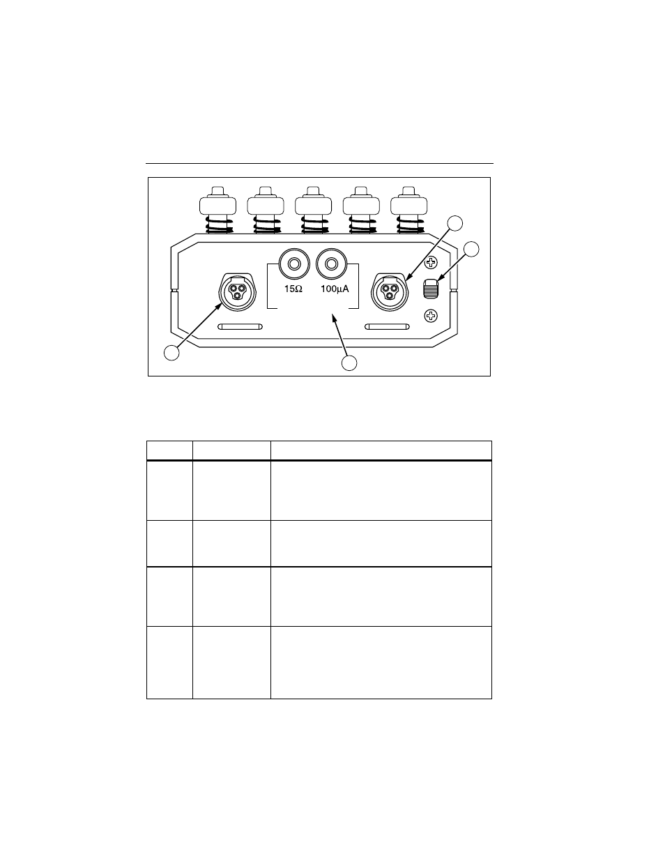
Figure 1-2. Analyzer Top Panel Components and Controls
Table 1-2. Components and Controls of the Analyzer
Label Name
Function
A
Power Cord
Supplies power to the Analyzer and to the DUT.
The measurement circuits are energized when
the power cord is plugged into an outlet. There is
no on/off switch.
B
Test Receptacle Supplies power to the DUT: DALE601, 15 A at
125 V
or DALE601, 20A at 125V;
and
DALE601E, 10 A at 230 V.
C
Outlet
Indicators
(DALE601 only)
Verifies the polarity and wiring of the outlet to
which the Analyzer is connected. Only correctly
wired outlets should be used. Not applicable to
isolated systems.
D
Outlet Switch
With the center OFF position, permits testing
with both the NORMAL (forward) and
REVERSED polarity of the line. It is
recommended that the switch is paused in the
center OFF position before changing polarity.