Measuring earth resistance – Fluke Biomedical DALE601 User Manual
Page 32
DALE601/601E
Operators Manual
2-8
Measuring Earth Resistance
Earth Resistance (R
G
) (grounding resistance) is the resistance from the DUT
conductive "grounded" chassis to the grounding terminal on the receptacle into
which it is plugged. Maintaining a low resistance is important to protect the
chassis from becoming "hot" with current as a result of an internal fault. The
resulting voltage drop across the ground wire raises the potential of the chassis
with respect to the local ground, creating a potential hazard.
The ground wire in the power cable is responsible for most of the resistance,
which is proportional to the cable length. See Table 2-1 for typical values for a
10-foot cable. The resistance measurement also includes the junction
resistance in connecting the wire at both ends and the bulk resistance of the
chassis from the grounding point to the point of measurement.
Low resistance values are being measured between the clip on the black
chassis cable and the grounding pin receptacle of the Analyzer. Therefore, the
Analyzer uses a four wire Kelvin bridge to make the measurement, avoiding
errors caused by the contact resistance of the cable connectors and the length
of the test cable.
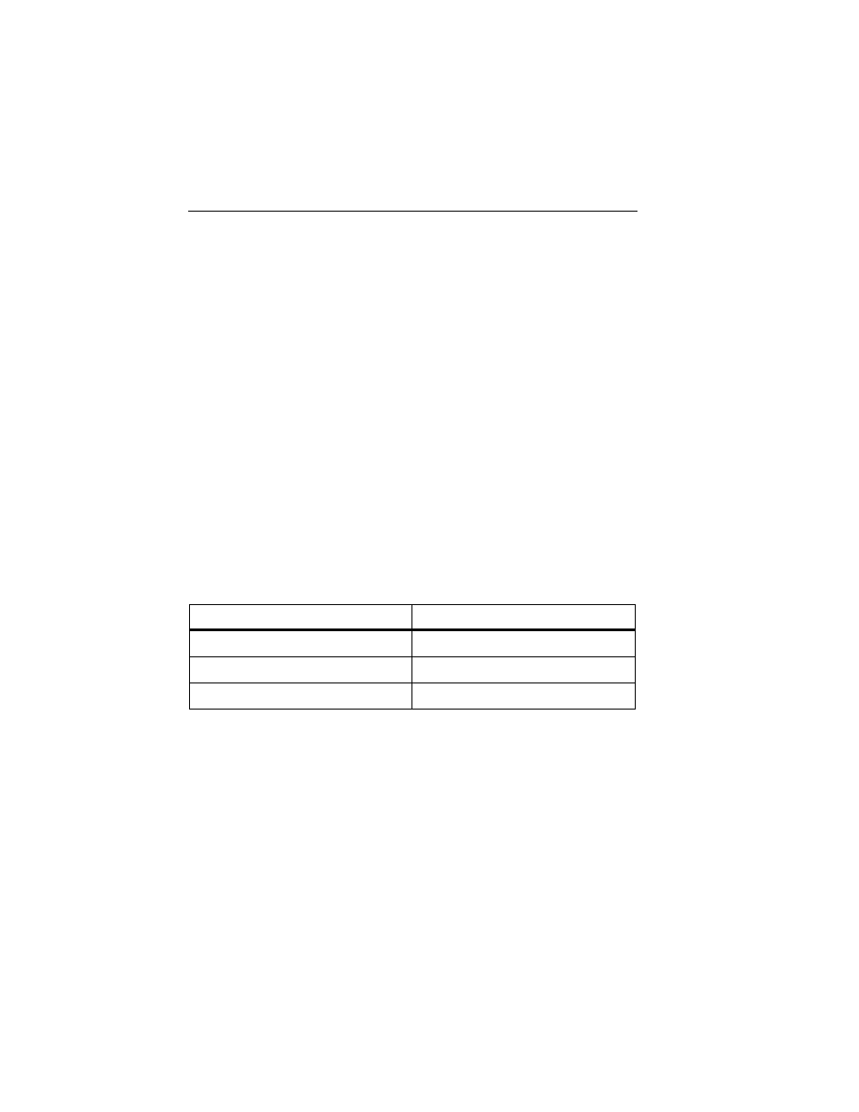
Table 2-1. Ground Resistance of a Ten-foot Power Cable
Wire Size (AWG)
Resistance (milliohms)
18 64
16 41
14 25
Note
Underwriters Laboratory (UL) limits the ground resistance for new
products to 100 m
Ω
(0.1
Ω
), and the National Fire Protection
Association (NFPA) limits ground resistance to 150 m
Ω
for new
products and 500 m
Ω
for devices in the field.
To measure earth resistance:
Note
This test is applicable only to devices using three-wire (grounded)
power cords.