Measuring map (patient lead isolation) current – Fluke Biomedical DALE601 User Manual
Page 40
DALE601/601E
Operators Manual
2-16
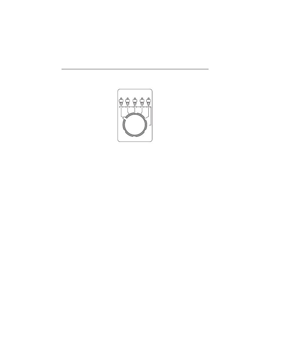
3. Select by the
LEADS
switch to test individual leads.
LEADS
fcu12.eps
4. Make measurements under all combinations of the
OUTLET
switch,
NORMAL
and
REVERSE
; the
NEUTRAL
switch
CLOSED
and
OPEN
;
GROUND CLOSED
and the
LIFT
GROUND
switch
OPEN
;
and the device power turned
ON
and
OFF
.
Under normal conditions, the current is primarily input bias current,
measuring current or leadoff sensing current. The worst case condition is
measured from the individual lead to all other leads connected together.
The single lead carrying the most current is generally considered the
reference lead (RL) because it acts as the return for the other leads.
Therefore, the leads can be taken in groups of four with the common
reference lead (RL) and then summed.
Measuring MAP (Patient Lead Isolation) Current
MAP (Mains on Applied Parts) Current (I
I
) (patient lead isolation current) is
that which would flow into the DUT if the patient were to come into contact
with full line voltage. An example is an electric patient bed that has become
ungrounded and has a short to the frame.
Measurement is made in each individual leads, but a common value is found
for all leads, as well as for the
ALL
position, as this is the measurement for the
isolation of the patient circuit. To assure proper reading, the test should be run
with ground intact. For additional safety, the current is applied to the patient
leads only when the
ISO TEST
switch is pressed.