Electrical isolation, 20 2. set the function switch to external – Fluke Biomedical DALE601 User Manual
Page 44
DALE601/601E
Operators Manual
2-20
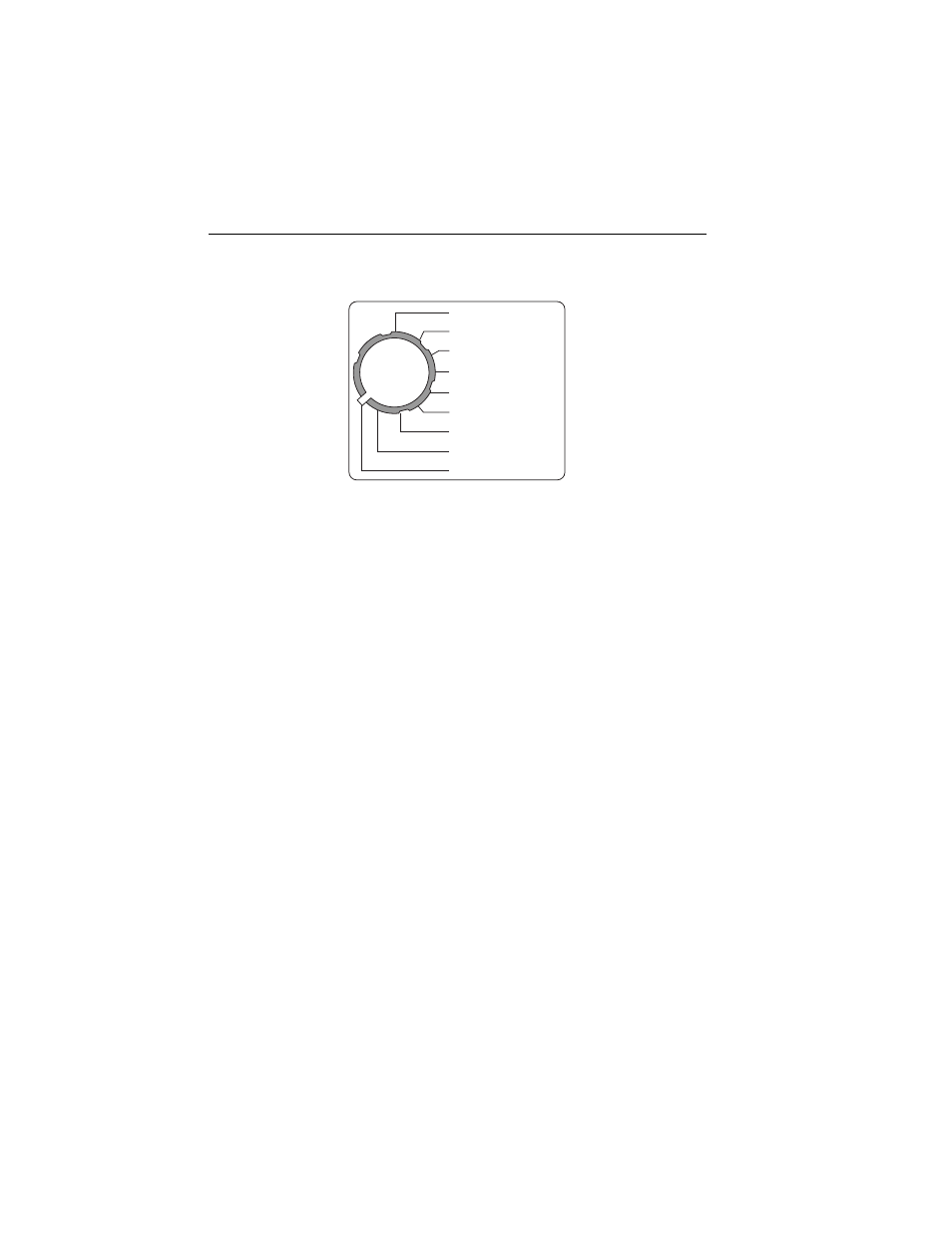
2. Set the
FUNCTION
switch to
EXTERNAL.
MAI
N
S
V
OLTAGE
CURRE
N
T AMPS
EARTH RESISTA
N
CE
EARTH LEAKAGE
E
N
CLOSURE LEAKAGE
PATIE
N
T LEAD LEAKAGE
PATIE
N
T AUX CURRE
N
T
M.A.P.
EXTER
N
AL
fcu11.eps
3. Clip the cables to the two points for which leakage current is to be
measured.
The Analyzer displays the leakage current between the two points to 1999
µA. The number displayed is also the voltage gradient in mV between the
two points, based on a voltmeter with an input impedance of 1000
Ω
.
Electrical Isolation
Isolation testing of probes and transducers that make internal contact to a
patient is provided to assure the reliability of the isolation barrier. Such devices
incorporate electrical circuits that can introduce or sink hazardous currents to a
patient who comes into contact with line potential or who becomes grounded.
Note
For devices that require sterilization before use, testing before
sterilization is recommended.
To measure electrical isolation of a probe or transducer:
1. Connect the black coil cord cable with the clamp with black insulation to
the
CHASSIS
connector and the black cable with the clamp with red
insulation to the
EXTERNAL
connector on the top panel of the Analyzer.