Test tone generator module, Description, Set-up – GAI-Tronics 12389-001 NOVA PA/GA Systems S.M.A.R.T. Modules User Manual
Page 13
Pub. 42004-674L2H
NOVA
P
UBLIC
A
DDRESS
S
YSTEMS
-
S.M.A.R.T.
M
ODULES
P
AGE
11 of 24
f:\standard ioms - current release\42004 instr. manuals\42004-674l2h.doc
12/13
Test Tone Generator Module
Description
The GTC 69393-101 Test Tone Generator Module is a key component of an S.M.A.R.T. Module system.
It provides the tone signal generation and a method to mix the tone signal into the required audio
pathways. It provides a tone used as a generator for an inaudible source of power to the Speaker Remote
Modules, when used.
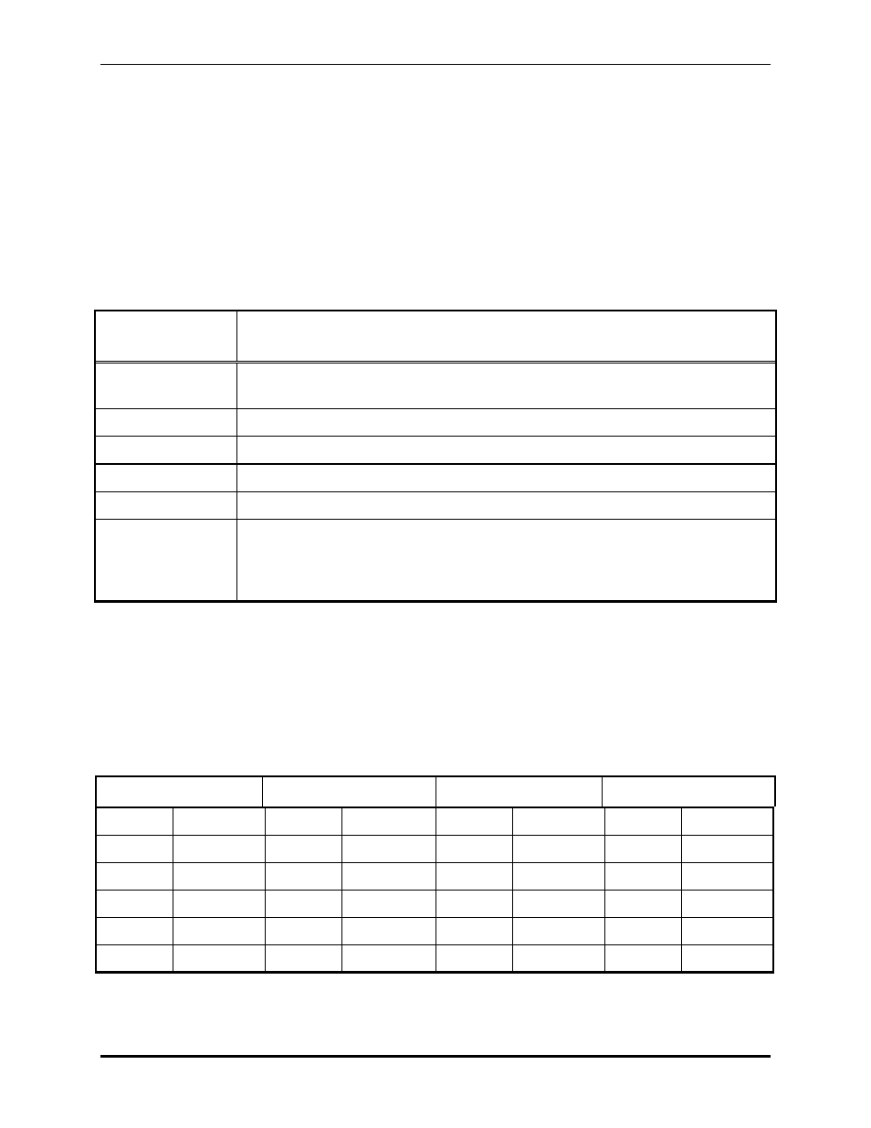
The Test Tone Generator module contains the following controls and indicators:
Table 3. Test Tone Generator Controls and Indicators
Control or
Indicator
Function
Communication
Indicator LED
This LED lights when the module is communicating with the Speaker Master.
P5
This jumper puts the Test Tone Generator into the Diagnostic mode.
P6
This jumper resets the Test Tone Generator.
J1
This jumper adds a terminating resistor to the RS-485 line.
P1 through P4
These jumpers connect a 600-ohm terminating resistor to the input of each channel.
CH1-R21,
CH2-R28,
CH3-R39,
CH4-R44
These individual potentiometers are used to set the individual tone output levels.
Set-Up
Refer to the board layout diagram.
1. Make the low level audio input and output connections for up to four channels at TB1, TB2, TB3, and
TB4 as follows:
Table 4.
Channel 1
Channel 2
Channel 3
Channel 4
TB1-1 Shield
GND
TB2-1 Shield
GND
TB3-1 Shield
GND TB4-1 Shield
GND
TB1-2 Line
output
TB2-2 Line
output
TB3-2 Line
output
TB4-2 Line
output
TB1-3 Line
output
TB2-3 Line
output
TB3-3 Line
output
TB4-3 Line
output
TB1-4 Line
input TB2-4 Line
input TB3-4 Line
input TB4-4 Line
input
TB1-5 Line
input TB2-5 Line
input TB3-5 Line
input TB4-5 Line
input
TB1-6 Shield
GND
TB2-6 Shield
GND
TB3-6 Shield
GND TB4-6 Shield
GND
2. Make the 24 V dc power connections at TB5. The polarity is noted on the board.
- 69389-010 NOVA PA/GA Systems S.M.A.R.T. Modules 12399-001 NOVA PA/GA Systems S.M.A.R.T. Modules 69403-101 NOVA PA/GA Systems S.M.A.R.T. Modules 13317-002 NOVA PA/GA Systems S.M.A.R.T. Modules 69389-020 NOVA PA/GA Systems S.M.A.R.T. Modules 12395-001 NOVA PA/GA Systems S.M.A.R.T. Modules 13317-001 NOVA PA/GA Systems S.M.A.R.T. Modules 12604-014 NOVA PA/GA Systems S.M.A.R.T. Modules