Operation, Normal mode – GAI-Tronics 12389-001 NOVA PA/GA Systems S.M.A.R.T. Modules User Manual
Page 8
Pub. 42004-674L2H
NOVA
P
UBLIC
A
DDRESS
S
YSTEMS
-
S.M.A.R.T.
M
ODULES
P
AGE
6 of 24
f:\standard ioms - current release\42004 instr. manuals\42004-674l2h.doc
12/13
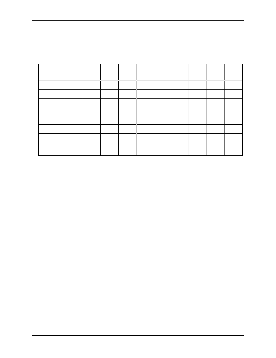
Set the LIM for either internal or external control. Internal or external control mode is determined by the
setting of the address jumpers JU2, JU3, JU4, and JU5. These are connected in binary fashion and
determine the serial network address of each individual LIM.
N
OTE
: These settings cannot be duplicated when external control is used for multiple LIMs.
Table 1.
Network
Address
JU2
JU3
JU4
JU5
Network
Address
JU2
JU3
JU4
JU5
0
8
X
1
X
9
X X
2
X
10
X X
3
X X
11
X X X
4
X
12
X
X
5
X X
13
X X X
6
X X
14
X X X
7
X
X
X
15
(Free-run Mode)
X X X X
X indicates the jumper is installed.
5. If applicable, connect RS-485 for external communication with CPU using the 8-pin modular
connectors J4 and J1 on the LIM controller PCBA.
Operation
The LIM has two operational modes: the Normal (measurement) mode and the Programming mode. The
Programming mode is selected by inserting a shorting jumper, JU1. Removing the jumper returns the
LIM to the Normal mode.
Normal Mode
In the Normal mode, at a pre-programmed time interval, the microprocessor selects one of the eight
monitored lines at a time, applying a specific dc current through the line dc loop, and measures the loop
voltage. If the measured voltage falls within predetermined limits (as defined in the Program mode), the
line loop resistance is determined to be within tolerance.
If not, an alarm is initiated as a line-unique logic closure. An LED indication is physically linked to the
alarm closure. If the loop voltage is too high, (above tolerance) the line is assumed to be wholly or in
part, “open.” If the loop voltage is too low the line is assumed to be wholly or in part, “shorted.”
In either case, the out-of-tolerance condition is retained in RAM for further processing as described
below. The leakage test is then applied to the line. An out-of-tolerance failure is indicated by a logic
output from a leakage comparator. The fault determination is a hardware function.
- 69389-010 NOVA PA/GA Systems S.M.A.R.T. Modules 12399-001 NOVA PA/GA Systems S.M.A.R.T. Modules 69403-101 NOVA PA/GA Systems S.M.A.R.T. Modules 13317-002 NOVA PA/GA Systems S.M.A.R.T. Modules 69389-020 NOVA PA/GA Systems S.M.A.R.T. Modules 12395-001 NOVA PA/GA Systems S.M.A.R.T. Modules 13317-001 NOVA PA/GA Systems S.M.A.R.T. Modules 12604-014 NOVA PA/GA Systems S.M.A.R.T. Modules