Alc remote module, Description – GAI-Tronics 12389-001 NOVA PA/GA Systems S.M.A.R.T. Modules User Manual
Page 20
Pub. 42004-674L2H
NOVA
P
UBLIC
A
DDRESS
S
YSTEMS
-
S.M.A.R.T.
M
ODULES
P
AGE
18 of 24
f:\standard ioms - current release\42004 instr. manuals\42004-674l2h.doc
12/13
ALC Remote Module
Description
The ALC Remote Module, included in the GTC 12395-001 ALC Control Kit, is housed in a separate
enclosure in the logical subzone to be monitored.
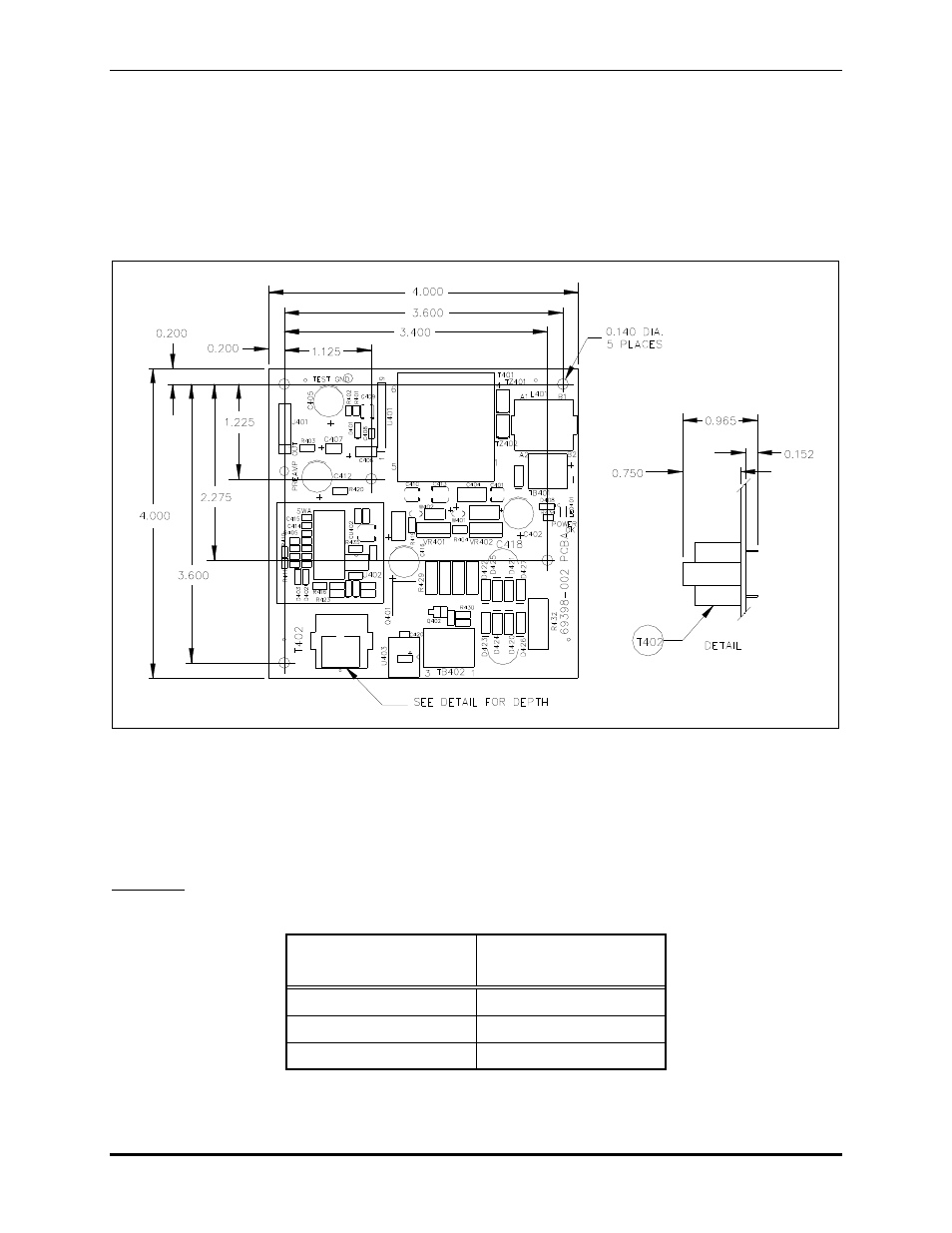
The location of the mounting holes on the 4.0
4.0-inch board are shown in Figure 2 below.
Figure 2. Mounting Dimensions for the ALC Remote Module PCBA
The dummy speaker or dynamic mic must be positioned close by to accurately sample the ambient noise
in the area. The remote is line-powered by the ALC Control Module, so an additional power source is
unnecessary. The wire line to the master must be of sufficient size to prevent significant resistance losses
to the phantom dc power. See the wire-size chart below.
Guideline: Total line resistance including both conductors must not exceed 20 ohms (10 ohm/wire)
Table 5. Wire Size Chart
Wire-run, Feet from
Master to Remote
Recommended
Minimum Wire Size
1000
No. 20 AWG
2000
No. 16 AWG
3000
No. 14 AWG
- 69389-010 NOVA PA/GA Systems S.M.A.R.T. Modules 12399-001 NOVA PA/GA Systems S.M.A.R.T. Modules 69403-101 NOVA PA/GA Systems S.M.A.R.T. Modules 13317-002 NOVA PA/GA Systems S.M.A.R.T. Modules 69389-020 NOVA PA/GA Systems S.M.A.R.T. Modules 12395-001 NOVA PA/GA Systems S.M.A.R.T. Modules 13317-001 NOVA PA/GA Systems S.M.A.R.T. Modules 12604-014 NOVA PA/GA Systems S.M.A.R.T. Modules