Set-up – GAI-Tronics 12389-001 NOVA PA/GA Systems S.M.A.R.T. Modules User Manual
Page 21
Pub. 42004-674L2H
NOVA
P
UBLIC
A
DDRESS
S
YSTEMS
-
S.M.A.R.T.
M
ODULES
P
AGE
19 of 24
f:\standard ioms - current release\42004 instr. manuals\42004-674l2h.doc
12/13
Set-Up
Install the enclosure for ALC Remote Module as close to the remote sensing speaker or microphone as
possible. Ensure the conduit entrances are sealed for protection from dust and moisture.
1. Connect the two wires from the remote sensing speaker/mic to TB402-1 and TB402-2. TB402-3 is a
shield connection. If a shield is used, it must be connected only to TB402-3 and not to the conduit.
2. Connect the two lines from the ALC Control Module.
Observe polarity. These carry the phantom line dc power and must be connected properly.
TB401-1 is dc positive. TB401-2 is negative.
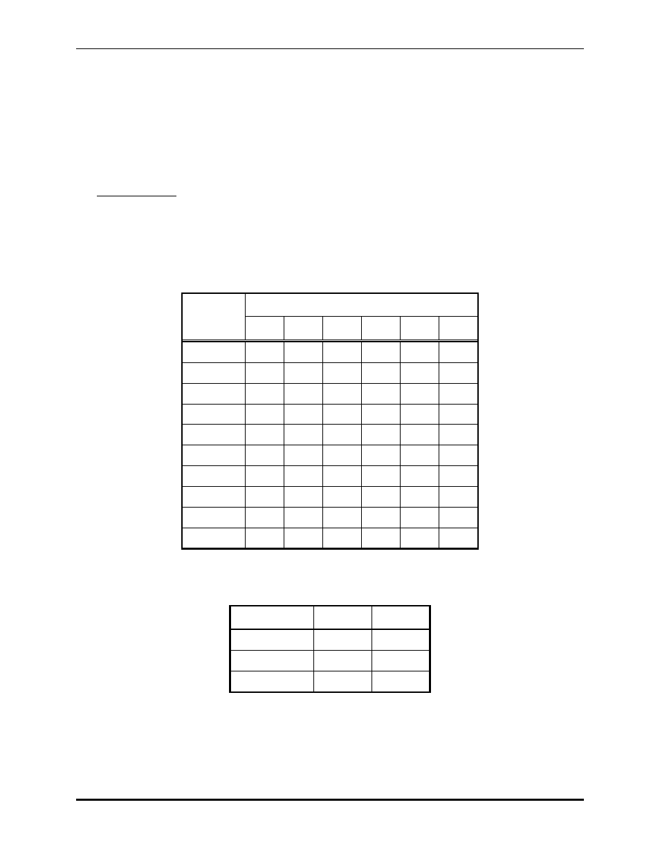
3. Adjust the amplifier gain settings. The remote sensing amplifier provides ten gain levels for
matching various sensing devices. The gain levels are listed in the table below. There are two high
frequency filter caps that can be switched in to provide noise bandwidth limiting.
Table 6.
Module
Gain
SWA Sections
−1
−2
−3
−4
−5
−6
45
ON
50
ON
ON
55
ON
60
ON ON
65
ON
70
ON ON
75
ON
80
ON ON
92
ON
97
ON
ON
Table 7.
Bandwidth* SWA-7 SW-8
1 ON
2
ON
3 ON
ON
*The high frequency bandwidth limiting function increases when used with higher gain.
- 69389-010 NOVA PA/GA Systems S.M.A.R.T. Modules 12399-001 NOVA PA/GA Systems S.M.A.R.T. Modules 69403-101 NOVA PA/GA Systems S.M.A.R.T. Modules 13317-002 NOVA PA/GA Systems S.M.A.R.T. Modules 69389-020 NOVA PA/GA Systems S.M.A.R.T. Modules 12395-001 NOVA PA/GA Systems S.M.A.R.T. Modules 13317-001 NOVA PA/GA Systems S.M.A.R.T. Modules 12604-014 NOVA PA/GA Systems S.M.A.R.T. Modules