GAI-Tronics CommandPLUS Series Desktop Console Installation and Service Manual User Manual
Page 43
CommandPLUS Series Desktop Console Installation and Service Manual Features and Options
39
12/10
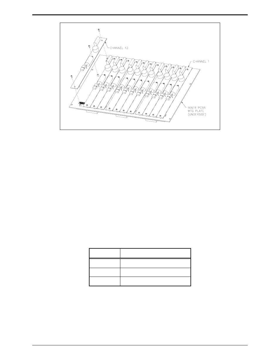
5. Mount the XCP0010A DC Control Option CDC board to the appropriate slave board (1, 2, or 3) and
channel (1, 2, 3, or 4 for each board). The CDC board must be mounted on the bottom side of the
slave panel.
6. Connect a 2-pin connector P62X on the CDC board to the appropriate header on the slave board
(JU620, JU621, JU622 or JU623).
7. Connect a 14-pin connector P2X to the 14-pin header (P26, P27, P28, or P29) on the CSD board.
8. Fasten the CDC board to the inner PCBA mounting plate using the three supplied #4-40 screws. See
Figure 17.
N
OTE
: A 2-pin header jumper must first be removed for this channel.
9. After the PCBAs have been properly mounted, you may reassemble the console by reversing the
disassembly procedure. Verify that all CSD-to-main board ribbon cables are properly positioned into
their protective guides and connected to their respective main board connectors as follows:
Table 14. Main Board-to-CSD Slave Board Connectors
Channel
Main Board Connector
1-4 P1
5-8 P2
9-12 P3
N
OTE
: The XCP0010A DC Control Option has been factory-calibrated to provide the standard
control currents and does not normally require field adjustment.
10. Reconnect power to the CommandPLUS Series Desktop Console.
After the console has been reassembled, it is necessary to program the console by editing the channel
parameters using the CARD Software.
Figure 17.