General set-up, Hardware configuration, Pcba adjustments – GAI-Tronics CB193-001 Call Boxes User Manual
Page 39: Microphone level, Speaker volume
Pub.: 43004-031E
Model CB193-xxx, CB194-xxx, and CB195-xxx RF Call Boxes
Page
38 of 52
f:\radio products-current release\43004\43004-031e\43004-031e.doc
11/12
General Set-Up
Hardware Configuration
PCBA Adjustments
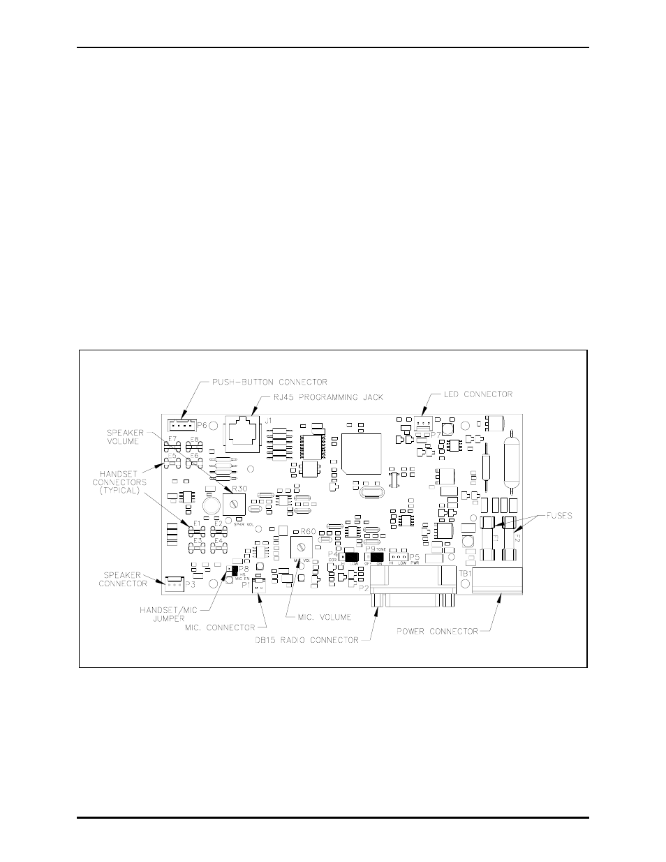
Microphone Level
The microphone (transmit) output level is adjusted using MIC VOL potentiometer, R60, located on the
RF Call Box PCBA. Refer to Figure 11. MIC VOL Test Point represents the signal entering the RF
module.
Speaker Volume
Speaker (receive) volume (Models CB193-xxx or CB195-xxx) or handset receiver volume (Model
CB194-xxx) can be adjusted using SPKR VOL potentiometer, R30, located on the RF Call Box PCBA.
Refer to Figure 11. SPKR VOL Test Point is a –15 dB test point for the signal supplied to the speaker
and a 0 dB test point for the signal supplied to the handset receiver. Maximum signal at the test point,
guaranteeing minimal distortion, is 180 mVrms.
Figure 11. RF Call Box PCBA