Connectors – GAI-Tronics CB193-001 Call Boxes User Manual
Page 41
Pub.: 43004-031E
Model CB193-xxx, CB194-xxx, and CB195-xxx RF Call Boxes
Page
40 of 52
f:\radio products-current release\43004\43004-031e\43004-031e.doc
11/12
Connectors
• Plug P1 connects the integrated microphone to the RF Call Box PCBA in Models CB193-xxx and
CB195-xxx.
•
Plug
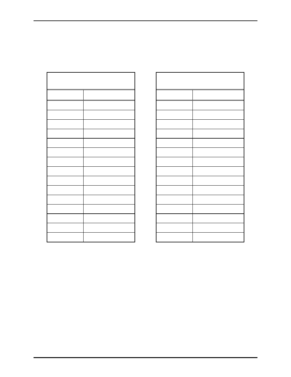
P2 connects the RF Module or 190-3170K Kit cable to the RF Call Box PCBA. Pin-out
information for P2 is as follows:
Models
CB19x-001 and CB19x-002
Model CB19x-003 with
190-3170K Adapter Kit
Pin Number
Function
Pin Number
Function
1 -
1 -
2 -
2 -
3 -
3 -
4 -
4 -
5 Power
Level
5
-
6 Power
6 Power
7
Audio TX
7
Audio TX
8 -
8 -
9 -
9 -
10 -
10 -
11
Tone Detect
11
Tone Detect
12
Audio RX
12
Audio RX
13
Carrier Detect
13
Carrier Detect
14 PTT
14 PTT
15 Ground
15 Ground
• Plug P3 connects the speaker to the RF Call Box PCBA in Models CB193-xxx and CB195-xxx.
•
Terminal Strip
TB1 connects the RF Call Box PCBA to its power source.
• Plug P6 connects the push-to-talk switch to the RF Call Box PCBA in Models CB193-xxx and
CB195-xxx.
• Programming Jack
J1 connects the PCBA to the computer for configuring the module for customer
specific operation using the CARD Suite Software application and the XAC0004A programming
cable.