Rs-485 junction box, Tb1 - rs-485 field wiring (unprotected) – Gasboy CFN Series Diagnostic Manual User Manual
Page 356
Site Controller III
12-22
1116
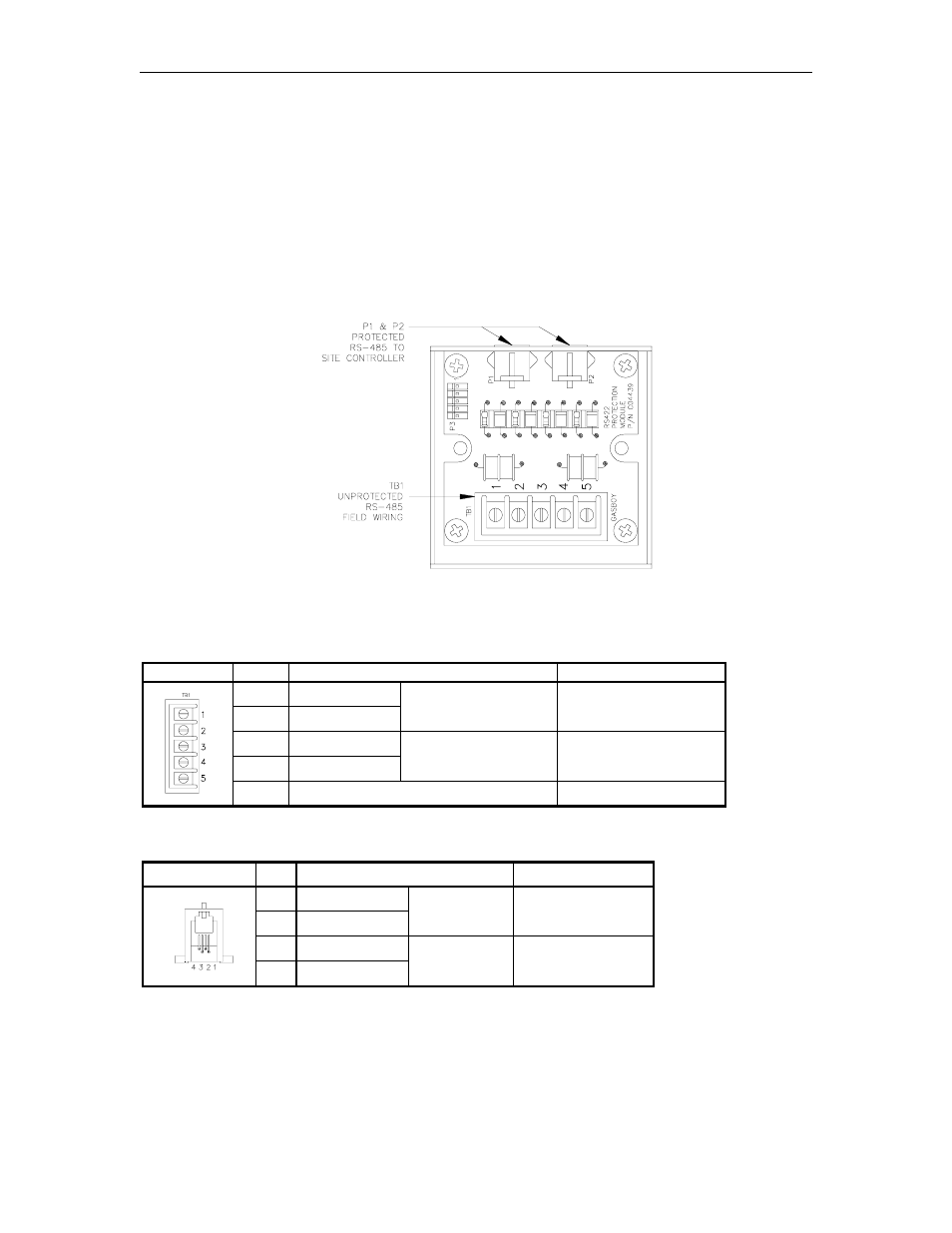
RS-485 JUNCTION BOX
The RS-485 junction box provides the interface for the RS-485 section of the site controller. This
unit:
•
provides the terminal block for field wiring of the RS-485 lines
•
provides protection against noise on the RS-485 lines
•
must be properly grounded
Layout
Connectors
TB1 - RS-485 Field Wiring (Unprotected)
Pinout
Pin
Function
Voltage
1
RS-485 Tx+
2
RS-485 Tx-
To Site Controller
+5 VDC signal
between pins 1 & 2
3
RS-485 Rx+
4
RS-485 Rx-
From Site Controller
+5 VDC signal
between pins 3 & 4
5
Ground
Ground
P1 & P2 - Protected RS-485 Signals to Site Controller
Pinout
Pin
Function
Voltage
1
RS-485 Rx+
2
RS-485 Rx-
To Site
Controller
+5 VDC signal
between pins 1 & 2
3
RS-485 Tx+
4
RS-485 Tx-
From Site
Controller
+5 VDC signal
between pins 3 & 4