GBS Elektronik MCA 166 User Manual
Page 10
_______________________________________________________________________
10
sample, amplifier setting 200*0.91, negative pulses, 1µs shaping time, pulse height
equals to about channel 662 of 1024 channels.
Typical errors which may be observed with the detector preamp signal are:
-Rise time is too slow (>0.5 µs). This may cause the pile up rejector not to work correctly.
There may be even a large amount of regular pulses rejected and especially the high
energetic part of the spectrum seriously affected. When using such detectors switch pile
up rejection off.
-The fall time is too fast (time constant resp. 1/e fall time < 40µs). This causes that the
pole/zero setting cannot be correctly adjusted. Consequences may be peak shift and
peak broadening with higher countrates and increased low energy spectrum cutoff. Try to
used another preamplifier.
2.2.6 Connecting the external additional battery pack
The additional battery pack can be used to extend measuring time up to 250% of that of
the stand-alone MCA (e.g. to 20 hours with a HPGe detector and to about 35 hours with a
NaI or CdZnTe detector. The “MCA” cable has to be plugged into the “Batt.” connector of
the MCA. By the electronics in the battery pack, charge exchange current between the
batteries is limited to 1A and reverse current (if an empty battery pack is connected to the
MCA) is inhibited. The current from the battery pack can be seen in the diagnostics menu
as “charger current”. The amount of current from the battery pack depends on voltage
differences between the batteries and the impedance off the MCA battery (about 1 Ohm).
If there is no current from the battery pack (or only something like 2 mA) then the voltage
of the battery pack is lower than voltage of the MCA battery. It should also be noted that
in the diagnostic menu only the amount and not the sign of a charging current is
registered. So a power consumer (e.g. a resistor) placed willfully at the “Batt.” connector
may be not distinguished from a power source.
The battery pack can be connected to a charger via the “Batt.” connector.
For even longer measurement times, infinite numbers of battery packs can be connected
in chain.
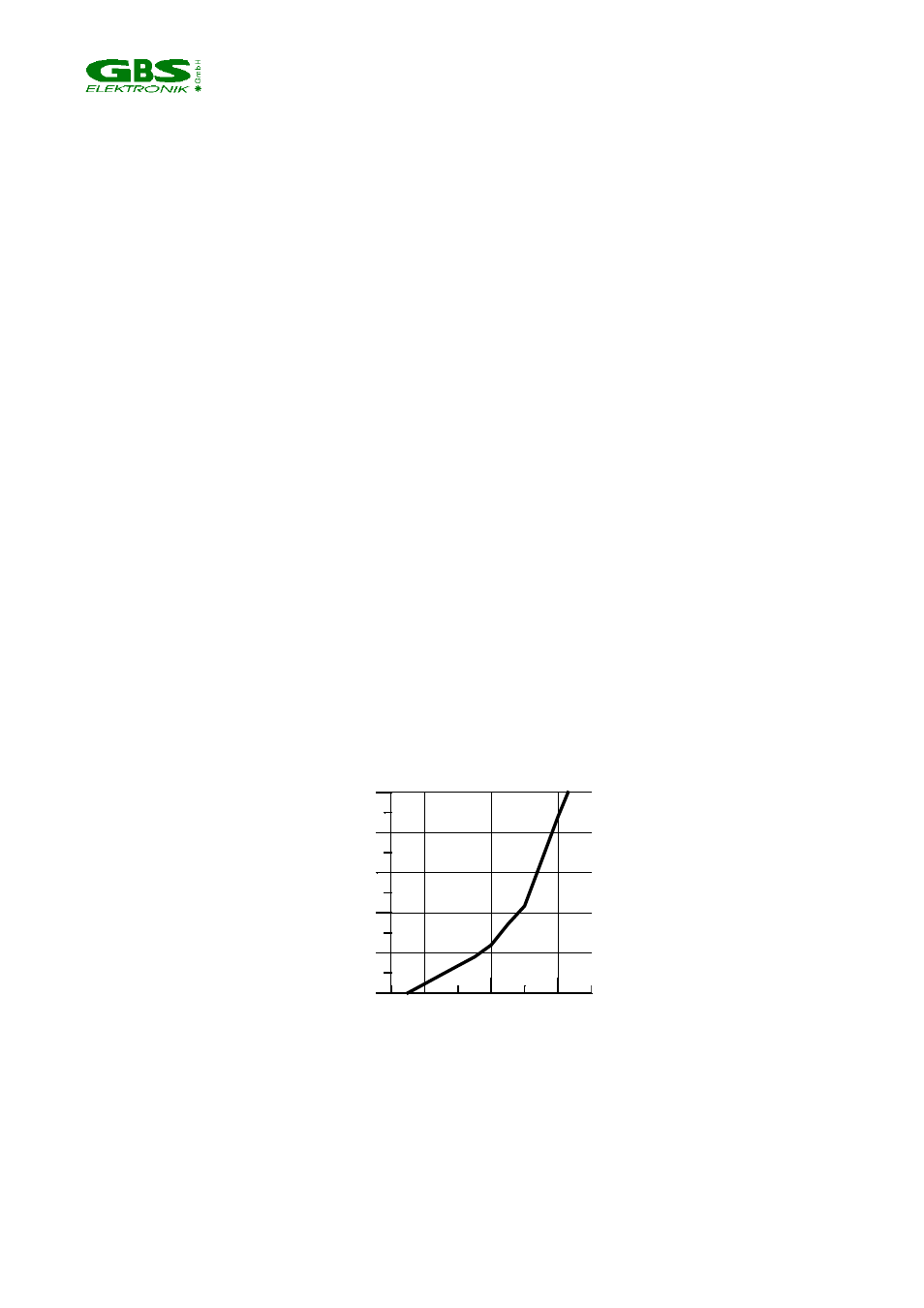
6
7
8
Battery Voltage (V)
0
20
40
60
80
100
B
a
tt
e
ry
C
h
a
rg
e
s
ta
te
(
%
)
Fig. 3: Charge state of the MCA battery in dependence of the battery voltage.
The charge state off the additional battery pack alone can be evaluated by measuring its
voltage at the “Batt.” connector. This is practically best done by plugging in the cable to
the charger with the connecting block on the charger side removed. Then the voltage can
be measured easily with a multimeter at the plug inserts of the connecting block.