Reference - control center layout, Reference - performance table – Greenheck IGK (472084) User Manual
Page 18
18
Model IGK Make-Up Air
®
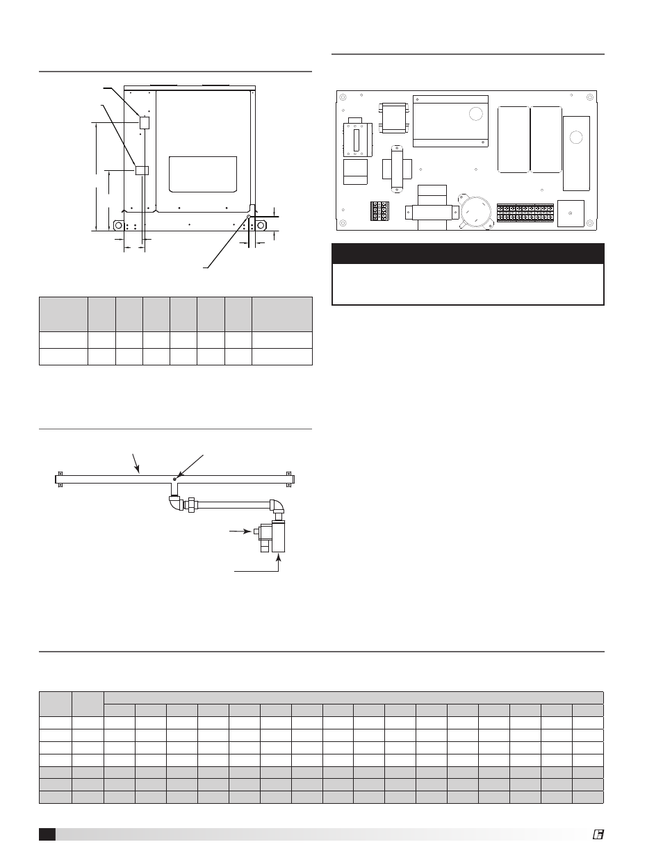
Reference - Venting Connection
Location
Reference - Typical Gas Train
Layout
Housing
A
B
C
D
E
G
Flue
Connection
H05
4.33
4.98
1.62
3.43 14.52 26.00
4.00
H15
8.09
7.38
3.87
3.62 15.43 28.37
6.00
Dimensions are in inches.
Reference - Control Center Layout
1. Supply Motor Starter - 24 volt magnetic
contacts for starting supply motor.
2. Supply Overload - Provides electronic overload
protection to supply motor.
3. Transformer - Provides voltage to combustion
blower.
4. Low Voltage Transformer (Optional) - Provides
low voltage to enable damper.
5. Combustion Fan Relay - Allows power to pass
to enable combustion fan on a call for heating.
6. Inlet Air Sensor - Outdoor air stat that
automatically controls the heating and/or cooling
based on outdoor air temperature.
7. Stage Controller - Provide two stages of control
based on discharge air temperature set point.
8. Ignition Controller - Controls the ignition and
maintains safe operation of the furnace.
9. Airflow Switch - Monitors the airflow inside the
heat exchanger to ensure proper combustion
airflow.
10. Time Delay - Allows furnace to ignite on high-
fire.
NOTE
Reference the ladder diagram on the inside of
the control center door for a unit specific wiring
diagram.
2
1
4
5
8
7
7
6
3
9
10
E
A
F
B
C
D
Disconnect
Exhaust Air
Outlet
3/4 inch gas connection
IGK HOUSING
A
B
C
D
E
F
H05
4.334
4.977
1.619
3.425
14.519
25.996
H15
8.094
7.378
3.868
3.618
15.433
28.372
H05
GAS
TRAIN
H15
GAS
TRAIN
Manifold
Gas Pressure
Test Port
Staged Gas Valve
3/4 inch Gas
Supply Connection
Manifold
Gas Pressure
Test Port
Staged Gas Valve
3/4 inch Gas
Supply Connection
Typical IGK Gas Train Layout
The following table gives the air volume in standard cubic feet per minute (SCFM) that is required to provide the
desired temperature rise for a given heating input. Model IGK has a maximum 5,000 CFM capacity.
Reference - Performance Table
Input
(MBH)
Output
(MBH)
Temperature Rise (ºF)
25
30
35
40
45
50
55
60
65
70
75
80
85
90
95
100
100
80
2963
2469
2116
1852
1646
1481
1347
1235
1140
1058
988
926
871
823
780
741
150
120
4444
3704
3175
2778
2469
2222
2020
1852
1709
1587
1481
1389
1307
1235
1170
1111
200
160
NA
4938
4233
3704
3292
2963
2694
2469
2279
2116
1975
1852
1743
1646
1559
1481
250
200
NA
NA
NA
4630
4115
3704
3367
3086
2849
2646
2469
2315
2179
2058
1949
1852
300
240
NA
NA
NA
NA
4938
4444
4040
3704
3419
3175
2963
2778
2614
2469
2339
2222
350
280
NA
NA
NA
NA
NA
NA
4714
4321
3989
3704
3457
3241
3050
2881
2729
2593
400
320
NA
NA
NA
NA
NA
NA
NA
4938
4558
4233
3951
3704
3486
3292
3119
2963
Venting Connection