3eko quick tour – LSC Lighting EKO User Manual
Page 10
EKO Dimmer
Operator Manual V2.3
Page 6
LSC Lighting Systems (Aust) Pty. Ltd
3
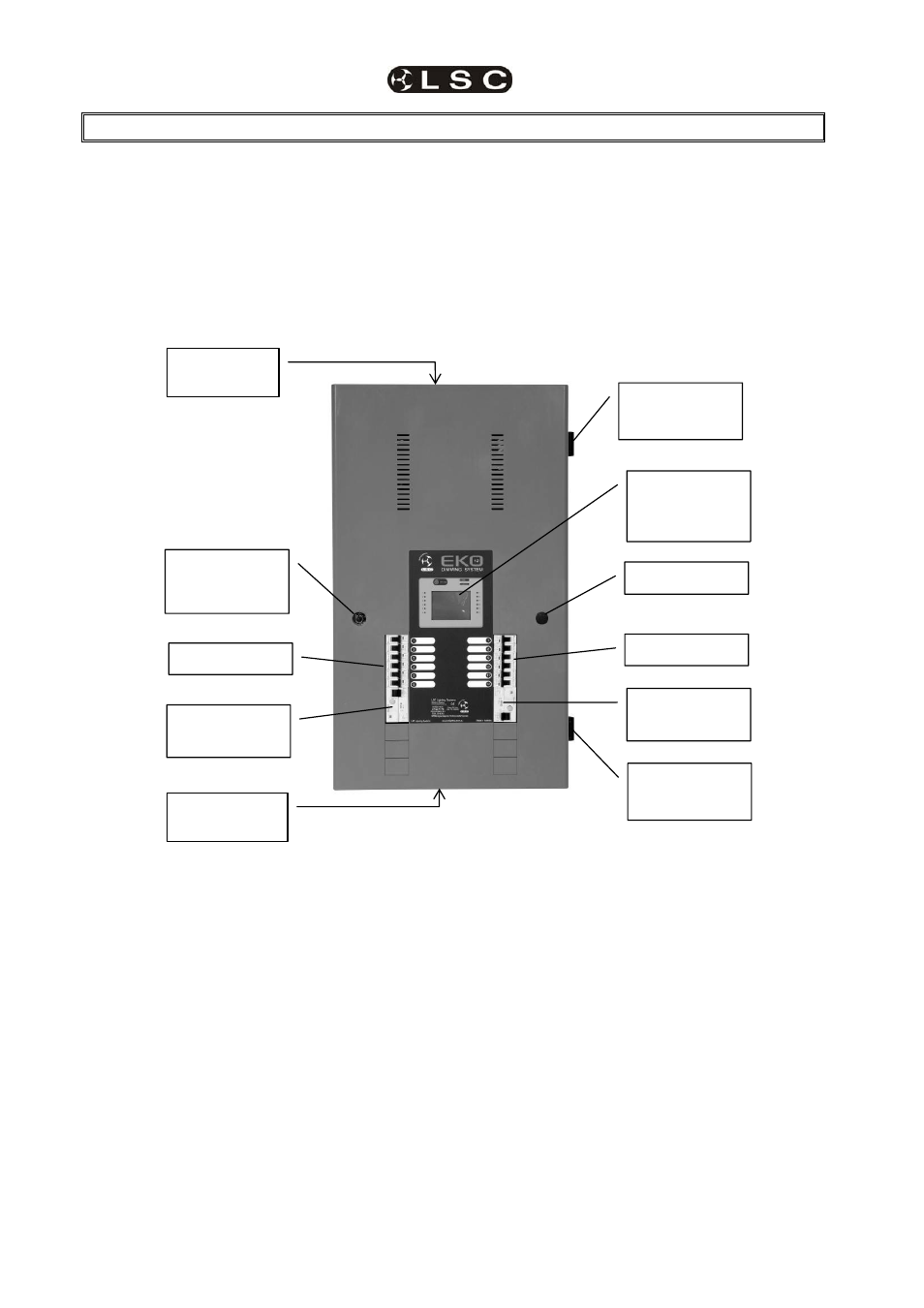
EKO Quick Tour
3.1 INTRODUCTION
All EKO models are constructed using two basic
cabinet sizes. Both cabinets have the same
width and depth, varying only in height.
• The tall cabinet is used for the EKO 612
and EKO 324.
• The short cabinet is used for the
EKO312
and EKO606
The front panel contains the input RCD circuit
breaker(s) (optional), load circuit breakers and
control panel that includes the status indicators
and LCD touch screen. The lockable front panel
provides internal access for installation and
maintenance. The front panel lock and hinges
can be reversed to swing the door in the
opposite direction.
No user serviceable parts are located inside.
EKO
612/R
3.1.1 Input RCD (Optional)
The optional three phase input RCD (Residual
Current Device) will cut the power to the EKO
dimmer if the residual current to earth at the input
exceeds 30 milliamps. It does not protect against
current overload. The input to the EKO must
always be connected to a suitably ratted external
circuit breaker even if the optional RCD is fitted.
See the specifications at the end of this manual
for the input ratings.
3.1.2 Output (Load) MCB’s
The load connected to each dimmer channel
output is protected by a numbered MCB
(Miniature Circuit Breaker). An area beside each
load MCB is provided to write the name of the
load.
Output
MCB’s
LCD Touch
Screen
Control Panel
Input RCD
(Optional)
Reversible
Front Panel
Lock
Reversible
Hinge
Cable Entry
Tunnel
Cable Entry
Tunnel
Output
MCB’s
Input RCD
(Optional)
Blanking Plate
Reversible
Hinge