LSC Lighting EKO User Manual
Page 12
Quick Tour
EKO Dimmer
Operator Manual V2.3
Page 8
LSC Lighting Systems (Aust) Pty. Ltd
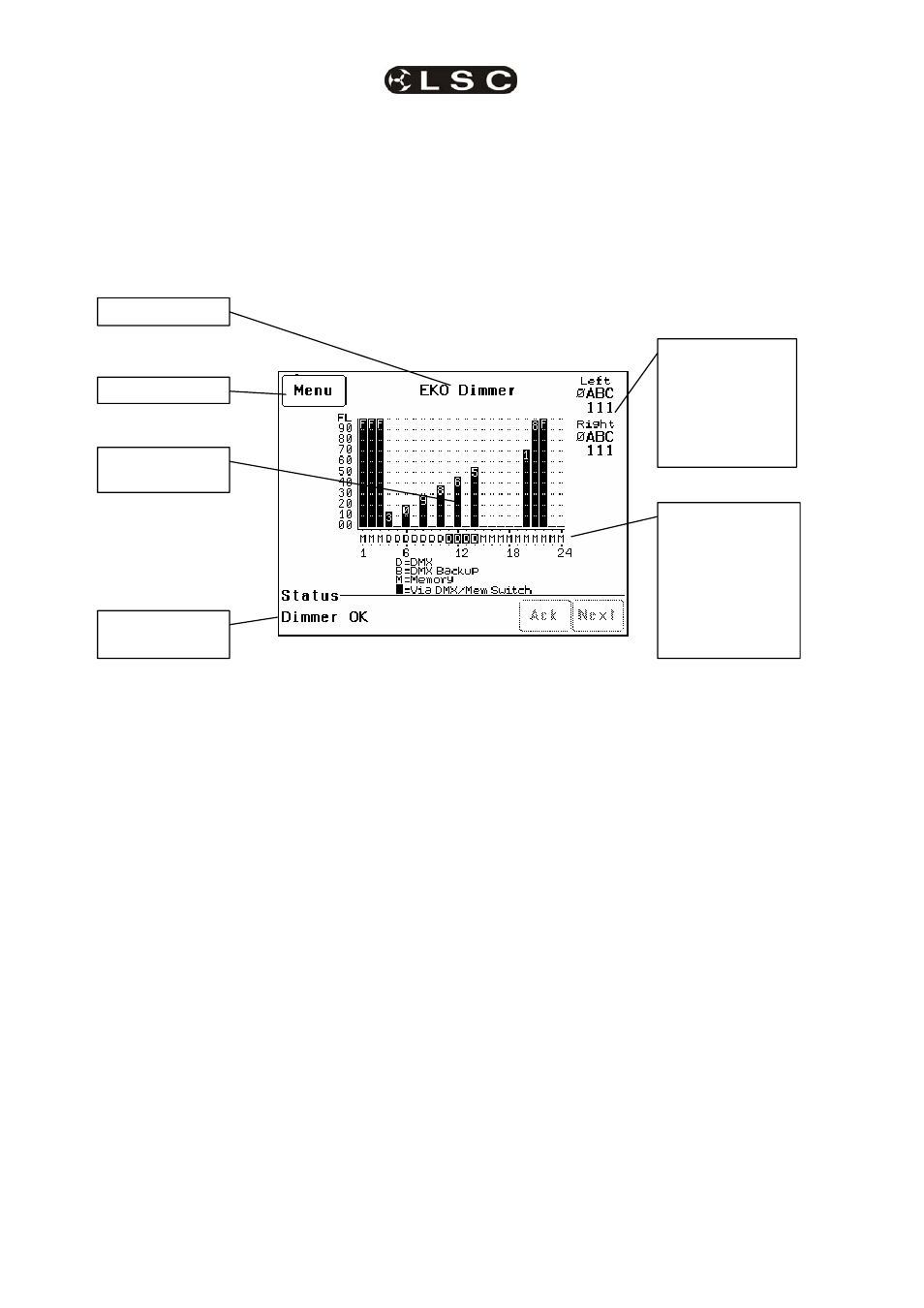
3.2.2 Touch Screen
The touch screen may be operated by touching
the virtual buttons with your finger. The home
page of the touch screen shows the current level
of each dimmer channel in a bar graph display.
If the EKO has been “locked”, the [Menu] button
is replaced by the [Unlock] button. Touching the
[Unlock] button and entering your code number
unlocks the EKO and reveals the [Menu] button.
Pressing [Menu] allows you to access a range of
functions, setups and tests via sub-menus. Each
sub-menu screen has help information in the top
left corner. The menus are fully described in
Section 7 “Menus”.
At the top of the screen is the name of this EKO
dimmer. The default name is “EKO Dimmer” but
you can enter a name of your choice from the
options menu. Names are useful in identifying
each EKO dimmer in installations containing
more than one EKO and can also be used by
the “Houston” monitoring software.
The middle of the screen is a bar-graph display
of the channel levels with channels numbers
shown across the bottom.
The levels from 00 to FL (Full) are shown on the
left scale in increments of ten, whilst the units of
each channel are shown on the individual
channel bars.
In the example above, channel 12 has a level of
46.
Channels can be individually configured to be
controlled from either “Memory” (ePlates),
“DMX” or “MEM/DMX Switch”. The letters below
the bargraphs show the control source for each
channel. The legend below the channel numbers
explains the meaning of the letters.
In the example above;
Channels 1 to 3 and channels 15 to 24 are
controlled by M (Memories recalled by ePlates).
Channels 4 to 10 are controlled by D (DMX).
Channels 11 to 14 (white letter on black
background) are also controlled by DMX but
control is via the MEM/DMX switch. Therefore
the switch is obviously in the DMX position. If
the switch was changed over to Memory, then
channels 11 to 14 would come under Memory
control.
If the switch has been set to “Auto Switch” to
DMX (if a DMX signal is present), then if the
DMX signal is lost, channels 11 to 14 would
automatically switch to Memory control.
See section 2.4 “EKO Control Philosophy” for
more details.
Depending upon the model of your EKO, it might
be fitted with one or two dimmer modules. The
EKO
312 and EKO 606 only have a “Left”
module whilst the EKO324 and EKO612 have
both “Left” and “Right” modules.
The right hand side of the screen indicates the
presence of the 3 phases (Ø A B C) of input
power at the “Left” and “Right” dimmer modules
inside the EKO.
“1” below a phase letter indicates the
presence of that phase
“Ø” below a phase letter indicates a loss
of that phase.
The bottom of the screen displays scrolling
messages about the status of the EKO dimmer.
These are described in the “Maintenance and
Alarms” section.
Letter shows
current control
source
for each
channel as per
legend on screen.
White text on black
shows control
source is via the
DMX/MEM Switch.
Status of Input
Power Phases A
B and C to Left
and Right (if fitted)
internal Modules.
1 = Present
0 = Not Present
Menu button
Scrolling Status
Messages
Channel level
bar-graph
Dimmer Name