LSC Lighting EKO User Manual
Page 20
ePlate and LSCnet Installation
EKO Dimmer
Operator Manual V2.3
Page 16
LSC Lighting Systems (Aust) Pty. Ltd
Each additional EKO dimmer allows an
additional 4 ePlates to be powered (i.e. the
power supplies add together).
• 2 EKO Dimmers can power up to 8 ePlates.
• 3 EKO Dimmers can power up to 12 ePlates
If your installation exceeds the limits you will
need to add a “power booster”. Contact your
LSC agent for details.
5.5.2 Cable Limits
Up to 800 meters of Cat5 can be installed
before a data repeater is needed.
Maximum total of 800 metres of Cat5 cable.
If an installation requires more than 800m of
cabling then an LSCnet data repeater is
required. Contact your LSC agent for details.
5.5.3 Device Limits
In an EKO installation, every EKO dimmer and
every ePlate is known as a device.
A maximum of 32 devices can be connected to a
network before a data repeater is required.
Up to 65,535 devices can exist on an LSCnet
installation.
5.6 PROGRAMMING EPLATES
The functions of the buttons and faders on
ePlates can be programmed by a separate
computer program however ePlates are shipped
from the factory with pre-programmed standard
configurations that suit most requirements
See section 8; Memory (ePlate) Control, for
details on pre programmed ePlates and how to
customise the buttons and faders for special
requirements.
5.7 COMMISIONING LSCNET
The best approach to commission a network is
to activate it a small part at a time, and then
build on the working system. This ensures that
each device is working correctly before the next
device is added.
Start at the EKO dimmers, as they contain the
LSC Net Power Supply. Before installing the
ePlates in their remote locations, connect them
to the EKO via short Cat5 cables so you can
observe all devices on the network correctly
operating.
When all of the devices are working correctly,
disconnect the short Cat5 cables then gradually
build up the network by connecting the actual
network cabling, one ePlate at a time.
Connect the first ePlate and switch its
“terminate” switch to TERM. Check the ePlate
operation then switch its “terminate” switch to
UNTERM and connect the Cat5 cable that loops
onto the next (terminated) ePlate.
When that ePlate operates correctly, un-
terminate it then connect and test the next
ePlate.
When you are satisfied that the system works
correctly, screw in the ePlates.
5.8 REMOVING EPLATES
Each ePlate has a main processor board with a
small “LSC Net Connection Board” plugged into
the back of it. This “LSC Net Connection Board”
contains the two network RJ45 connectors and
the network termination switch.
If an ePlate needs to be removed for service or
testing, the LSC Net Connection Board can be
left in circuit, thus maintaining the network
integrity.
This feature also allows you to run all the
network cabling and join the cables using the
LSC Net Connection Boards without installing all
of the actual ePlates.
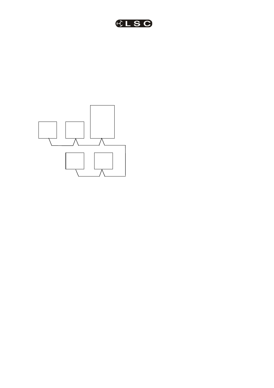
ePlate
EKO
Dimmer
ePlate
ePlate
ePlate
150m
250m
50m
350m