LSC Lighting EKO User Manual
Page 11
EKO Dimmer
Quick Tour
Operator Manual V2.3
LSC Lighting Systems (Aust) Pty. Ltd
Page 7
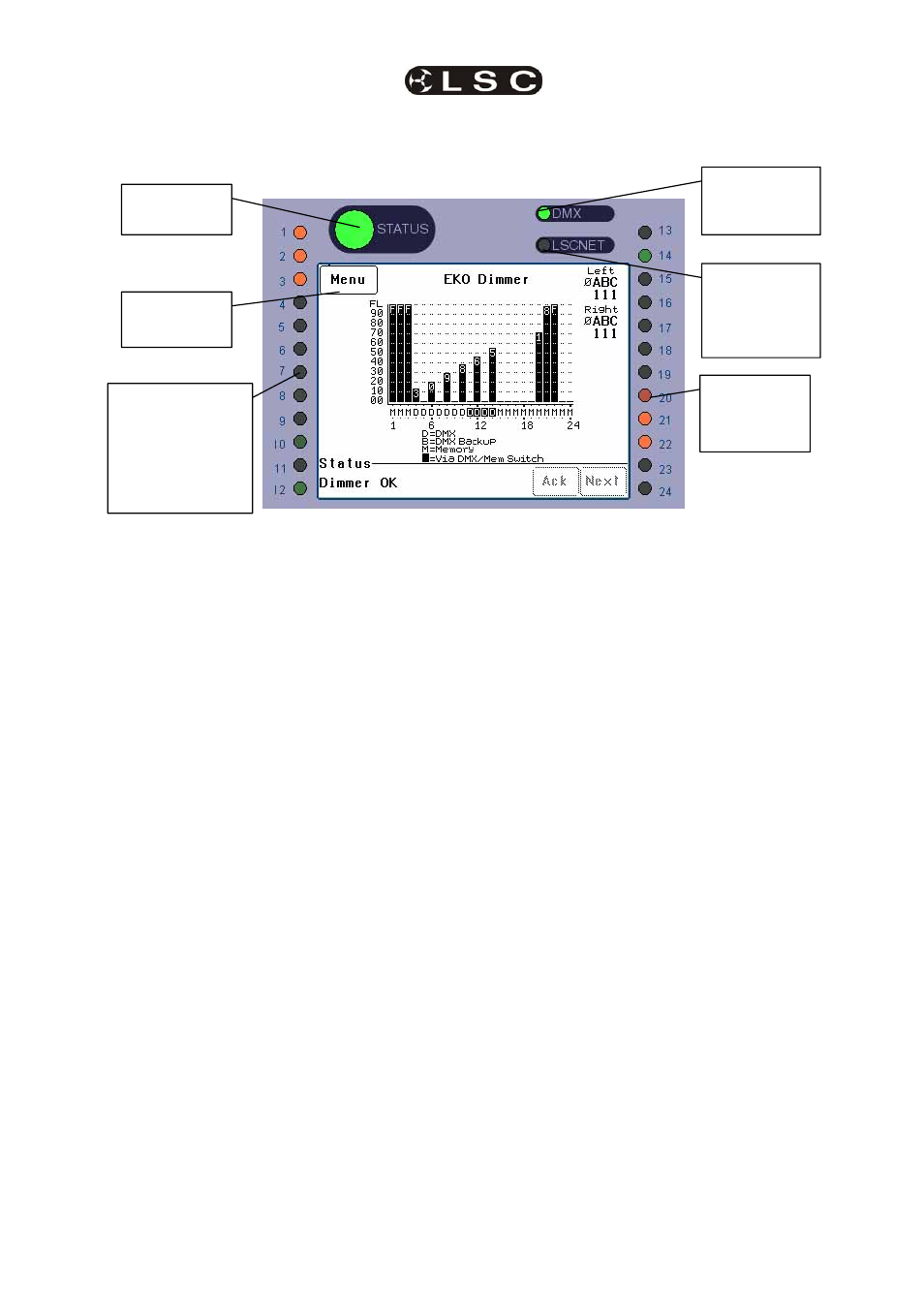
3.2 CONTROL PANEL
The Control Panel contains the indicators for status and channel levels and the LCD touch screen.
Illustration shows an EKO 324 Control Panel. Control panels on other models vary only in the quantity of
channel level indicators.
3.2.1 Indicators
The indicators located around the touch screen
are multi coloured and light or flash to indicate
their current condition as described below;
EKO STATUS
• Green = Normal operation.
• Red (flashing) = Alarm. See status
message on LCD screen.
• Red (steady) = Alarm is acknowledged
but the problem still exists.
DMX
• Green = Valid DMX control signal
connected.
• Green (flashing) = Loss of DMX control
signal.
• Red (flashing) = Error on DMX control
signal.
LSCnet
• Green = Valid LSCnet control signal
connected (from ePlates).
• Green (flashing) = Data traffic detected
on LSCnet.
CHANNELS
• Green = The channel is ON via DMX
control.
• Red = The channel is ON via memory
(ePlate) or channel test control.
The brightness of the channel indicator is
proportional to the channel level.
See the, “Maintenance and Alarms” section for
further details on alarms.
Channel level
indicators
1 to 12
Green = Controlled
by DMX
Red = Controlled
by Memory
LCD Touch
Screen
EKO Status
Indicator
DMX Remote
Control Status
Indicator
Channel level
indicators
13 to 24
(if fitted)
LSC Net
(ePlate)
Remote
Control Status
Indicator