LSC Lighting EKO User Manual
Page 24
Menus
EKO Dimmer
Operator Manual V2.3
Page 20
LSC Lighting Systems (Aust) Pty. Ltd
Reference source not found. “Patching” for
details.
2. Memory Control.
When configured for
“Memory Control” a dimmer channel is
controlled from ePlates (wall plates) that are
used to recall memories stored in the EKO
dimmer. These memories can be created and
edited via the LCD touch screen.
3. DMX/MEM Switch.
When configured to
“Switch”, a dimmer channel can be manually or
automatically switched between DMX or
Memory
control.
Manual
operation of the “DMX/MEM
Switch” is controlled either “remotely” from a
suitably programmed button on an ePlate or
“locally” from the EKO touch screen.
See section Error! Reference source not
found.
“DMX/MEM Switch Operation” for details
on how to manually operate the “DMX/MEM
Switch” from the touch screen.
Automatic
operation of the “Switch” is
controlled by the presence or absence of a valid
DMX signal from a DMX lighting controller.
When DMX is present it will be automatically
connected to any channels that are set to
“Switch”.
See 7.3.6.2 “DMX/MEM Switch Connect Loss
Action” for details on how to set the “DMX/MEM
Switch” to “Auto Switch” to DMX.
When finished press [Save Setup] [Done]
[Done].
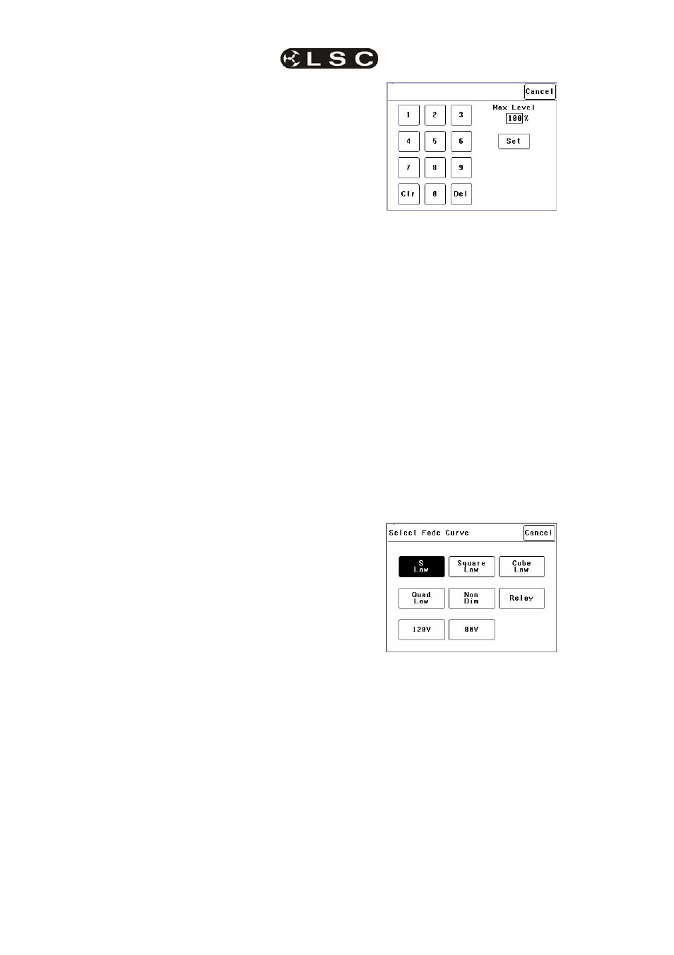
7.2.1.2 MIN AND MAX LEVEL
The “Min Level” attribute sets the level of the
dimmer output when the control signal is set to
minimum. Setting this value slightly above zero
is useful to “Pre-Heat” lamp filaments.
“Max Level” sets the level of the dimmer output
when its control signal is set to maximum.
Press; [Menu] [Dimmer Channels] [Setup] then
use the § and ¨ buttons to select “Min Level” or
“Max Level”.
When you select a channel(s) (by touching it)
then press [Min Level] or [Max Level], you can
use the keypad that appears to enter the
required percentage level for the selected
channels, then press [Set].
When finished press [Save Setup] [Done]
[Done].
7.2.1.3 FADE CURVE
Fade Curve is the curve or “transfer
characteristic” between input control signal and
dimmer output. The following curves are
available;
• S
Law
• Square
Law
• Cube
Law
• Quad
Law
• Non
Dim
• Relay
• 120V (Volt)
• 80V
(Volt)
Press; [Menu] [Dimmer Channels] [Setup] then
use the § and ¨ buttons to select “Fade Curve”.
When you select a channel(s) (by touching it)
then press [Fade Curve], you can select the
required curve for the selected channel(s).
“S Law” is the default law and provides a normal
dimmer response.
“Square”
, “Cube” and “Quad” laws can be
selected to better match the transfer
characteristic of existing dimmer installations or
to provide the response that you require. Try the
different curves to find the best curve for your
needs.
“Non Dim” is used for devices that do not fade,
but need to be switched OFF or ON such as
motors or discharge lamps.
When set to “Non Dim”, when the control signal
is raised above 60%, the dimmer will switch from
OFF to full ON and when the level drops below
40%, the dimmer will switch OFF.