Measurement Computing eZ-TOMAS version 7.1.x User Manual
Page 34
eZ-TOMAS & eZ-TOMAS Remote
887591
Edit Menu 3-8
Coupling
Each input can be AC or DC-coupled. The AC-Coupling High Pass Filter selection is
located on the Acquisition Tab. Proximity and Static Probes are typically DC-coupled.
All other types are usually AC-coupled. AC-coupling can be set to a high pass filter value
of 0.1 Hz or 1 Hz. The value is selected in the Edit Menu’s Acquisition Tab. Note that
when DC-Coupling is selected the high pass filter is bypassed.
When the Coupling function is not available to a channel, or not used by a channel, a dash
appears in that channel’s Coupling column.
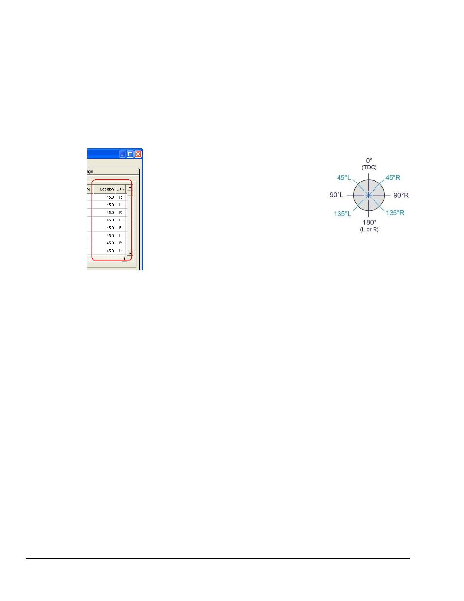
[Probe]
Location
L / R
The probe location and L/R columns are used to define
the physical angular location of a probe, from 0° to
180° left or right of Top Dead Center (TDC). The two
columns are in the Input Channels tab, as indicated in
the figure below. Probe location is used for Orbit,
Polar, and Shaft Center Line displays.
Note: Orientation of view is looking from the Driver
to the Driven. Zero degrees is always given as top
dead center (TDC). With eZ-TOMAS versions 5.5.09
and higher, the probe location is defined as “N”
degrees Left or Right of TDC. Projects created in
earlier versions of eZ-TOMAS defined location as
being CCW from TDC. That convention is
automatically converted to the newer one, represented
in the figure at the right.
1xA Ref and
1xP Ref
1x Amplitude Reference and 1x Phase Reference are the slow roll values used for Runout
Compensation on Bode, Polar, Time Waveform, or Orbit displays.
Gap Volt
is the DC voltage value when the shaft is at rest. This value is used for Shaft Center Line
displays.
XY
Pair
XY Pair associates 2 probes on a bearing. Typically, probe pairs are located 90 degrees
apart. Orbit and Shaft Centerline displays require a Channel Pair.
Brg Clear
Bearing Clearance is measured in the instrument’s engineering units. You can
optionally overlay the bearing clearance circle onto an orbit display or shaft centerline.
Brg Start
Bearing Start is the location of the shaft relative to the bearing when the machine is at
mechanical rest. Three possible locations are taken into consideration: Bottom, Center,
and Top. For horizontal shafts, a bearing start of bottom is typical, due to gravity;
However, in some situations mechanical linkage can result in a bearing start with the shaft
at the top. For shafts that are oriented vertically, a bearing start of center is likely.
Tach
Reference
This column defines allows you to define a reference tachometer for each channel. Thus,
on Gauge Display and Plot Display eZ-TOMAS can show 1x values relative to the
preferred tach. When two or more tachs are defined eZ-TOMAS computes spectral data
relative to each. For example, with two tachs: If Tach 1 measures 3000 rpm and Tach 2
measures 4500 rpm eZ-TOMAS computes 1xA values for each. With the RPMs given,
the resulting 1x Frequency values are 50 Hz for Tach 1 and 75 Hz for Tach2.
Clicking the Tach Reference column brings up a pull-down list which indicates the
tachometer channels available for use as reference [for the currently displayed data].